Infiniti EX35. Manual - part 1443


  Index      Infiniti     Infiniti EX35 - service repair manual 2008 year


Search            


Content   ..  1441  1442  1443  1444   ..


Infiniti EX35. Manual - part 1443


TM-160

< ON-VEHICLE REPAIR >

[5AT: RE5R05A]

CONTROL DEVICE

b.

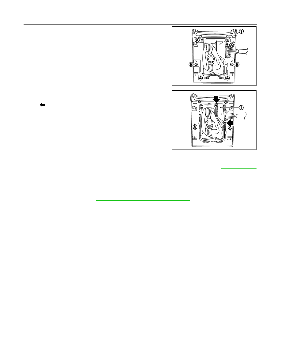
Remove insert finisher (1) from console finisher assembly.

c.

Remove the selector lever position indicator (1).

15. Remove adapter from control device assembly.
16. Remove dust cover and dust cover plate from control device

assembly.

17. Remove dust cover plate from dust cover.
18. Remove shift lock unit from control device assembly.

19. Remove bracket from vehicle floor panel.

INSTALLATION

Note the following, and install in the reverse order of removal.
• When installing control rod to control device assembly, refer to “ADJUSTMENT”. Refer to 

TM-153, "AWD :

Inspection and Adjustment"

.

AWD : Inspection and Adjustment

INFOID:0000000003130605

INSPECTION AFTER INSTALLATION

Check the A/T positions. Refer to 

TM-153, "AWD : Inspection and Adjustment"

.

A

: Screw (small)

B

: Screw (large)

JPDIA0636ZZ

: Screw

JPDIA0637ZZ

CONTROL ROD

TM-161

< ON-VEHICLE REPAIR >

[5AT: RE5R05A]

C

E

F

G

H

I

J

K

L

M

A

B

TM

N

O

P

CONTROL ROD

Exploded View

INFOID:0000000003130606

Removal and Installation

INFOID:0000000003130607

REMOVAL

1.

Disconnect control device and control rod. Refer to 

TM-155, "2WD : Exploded View"

 (2WD models), 

TM-

158, "AWD : Exploded View"

 (AWD models).

2.

Remove manual lever from A/T assembly.

3.

Remove control rod from manual lever.

INSTALLATION

Note the following, and install in the reverse order of removal.
• When installing control rod to control device assembly, refer to “ADJUSTMENT”. Refer to 

TM-153, "2WD :

Inspection and Adjustment"

 (2WD models), 

TM-153, "AWD : Inspection and Adjustment"

 (AWD models).

Inspection and Adjustment

INFOID:0000000003130608

INSPECTION AFTER INSTALLATION

Check A/T positions. Refer to 

TM-153, "2WD : Inspection and Adjustment"

 (2WD models), 

TM-153, "AWD :

Inspection and Adjustment"

 (AWD models).

1.

Control rod

2.

Plain washer

3.

Manual shaft

4.

A/T assembly

5.

Manual lever

6.

Washer

7.

Snap pin

8.

Conical washer

9.

Insulator

10.

Collar

Refer to 

GI-4, "Components"

 for symbols in the figure.

JPDIA0638GB

TM-162

< ON-VEHICLE REPAIR >

[5AT: RE5R05A]

CONTROL VALVE WITH TCM

CONTROL VALVE WITH TCM

Exploded View

INFOID:0000000003130611

Removal and Installation

INFOID:0000000003130612

REMOVAL

1.

Disconnect the battery cable from the negative terminal.

2.

Drain ATF through drain plug.

3.

Remove exhaust mounting bracket. Refer to 

EX-5, "Exploded View"

.

1.

A/T

2.

Snap ring

3.

Sub-harness

4.

Bracket

5.

Control valve with TCM

6.

Bracket

7.

A/T fluid temperature sensor 2

8.

Oil pan gasket

9.

Clip

10. Oil pan mounting bolt

11.

Oil pan

12. Magnet

13. Drain plug

14. Drain plug gasket

15. Terminal cord assembly

16. O-ring

A.

For tightening torque, refer to “Installation”.

Refer to 

GI-4, "Components"

 for symbols in the figure.

JPDIA0646GB

CONTROL VALVE WITH TCM

TM-163

< ON-VEHICLE REPAIR >

[5AT: RE5R05A]

C

E

F

G

H

I

J

K

L

M

A

B

TM

N

O

P

4.

Disconnect heated oxygen sensor 2 harness connectors (A).

5.

Remove heated oxygen sensor 2 harness (B) from clips (1).

6.

Remove bracket (2) from transmission assembly.

7.

Disconnect A/T assembly harness connector.

8.

Remove snap ring (1) from A/T assembly harness connector
(A).

9.

Push A/T assembly harness connector (A).

CAUTION:

Be careful not to damage connector.

10. Remove clips (1).

11. Remove oil pan (2) and oil pan gasket.

12. Remove magnets (1) from oil pan.

: Vehicle front

: Bolt

SCIA8269E

JPDIA0007ZZ

JPDIA0008ZZ

3

: Drain plug

: Vehicle front

: Oil pan mounting bolt

SCIA8117E

JPDIA0009ZZ


Content   ..  1441  1442  1443  1444   ..