Content .. 1412 1413 1414 1415 ..
Infiniti EX35. Manual - part 1414
TM-44
< FUNCTION DIAGNOSIS >
[5AT: RE5R05A]
DIAGNOSIS SYSTEM (TCM)
1ST POSI IND (On/Off)
—
—
—
MANU MODE IND (On/Off)
—
—
—
POWER M LAMP (On/Off)
—
—
Not mounted but displayed.
F-SAFE IND/L (On/Off)
—
—
—
ATF WARN LAMP (On/Off)
—
—
Not mounted but displayed.
BACK-UP LAMP (On/Off)
—
—
—
STARTER RELAY (On/Off)
—
—
—
PNP SW3 MON (On/Off)
—
—
—
C/V CLB ID1
—
—
—
C/V CLB ID2
—
—
—
C/V CLB ID3
—
—
—
UNIT CLB ID1
—
—
—
UNIT CLB ID2
—
—
—
UNIT CLB ID3
—
—
—
TRGT GR RATIO
—
—
—
TRGT PRES TCC (kPa)
—
—
—
TRGT PRES L/P (kPa)
—
—
—
TRGT PRES I/C (kPa)
—
—
—
TRGT PRE FR/B (kPa)
—
—
—
TRGT PRES D/C (kPa)
—
—
—
TRG PRE HLR/C (kPa)
—
—
—
SHIFT PATTERN
—
—
—
DRV CST JUDGE
—
—
—
START RLY MON
—
—
—
NEXT GR POSI
—
—
—
SHIFT MODE
—
—
—
MANU GR POSI
—
—
—
VEHICLE SPEED (km/h)
—
X
Vehicle speed recognized by the TCM.
1 POSITION SW (On/Off)
X
—
Not mounted but displayed.
OD CONT SW (On/Off)
X
—
HOLD SW (On/Off)
X
—
BRAKESW (On/Off)
X
—
Stop lamp switch
POWERSHIFT SW (On/Off)
X
—
Not mounted but displayed.
ASCD-OD CUT (On/Off)
—
—
—
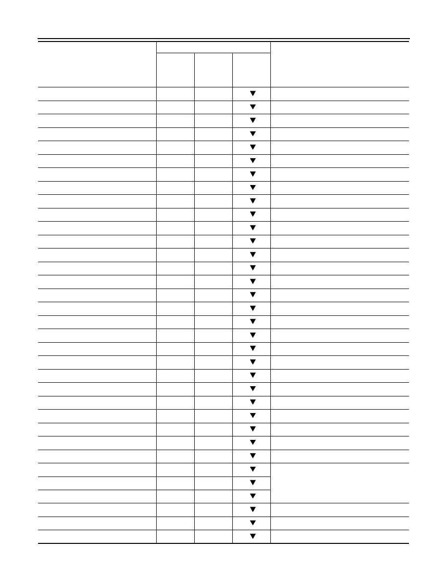
Monitored item (Unit)
Monitor Item Selection
Remarks
ECU IN-
PUT SIG-
NALS
MAIN SIG-
NALS
SELEC-
TION
FROM
ITEM