Infiniti EX35. Manual - part 1413


  Index      Infiniti     Infiniti EX35 - service repair manual 2008 year


Search            


Content   ..  1411  1412  1413  1414   ..


Infiniti EX35. Manual - part 1413


TM-40

< FUNCTION DIAGNOSIS >

[5AT: RE5R05A]

DIAGNOSIS SYSTEM (TCM)

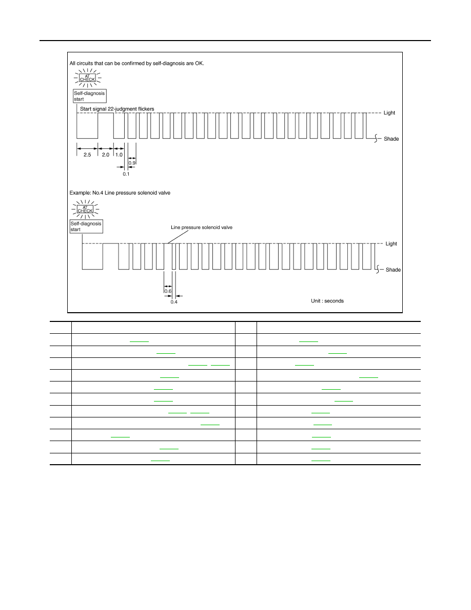
If there is a malfunction, the lamp lights up for the time corresponding to the suspect circuit.

Erase Self-diagnosis

In order to make it easier to find the cause of hard-to-duplicate malfunctions, malfunction information is stored
into the control unit as necessary during use by the user. This memory is not erased no matter how many
times the ignition switch is turned ON and OFF. 
However, this information is erased by turning ignition switch OFF after performing self-diagnostics or by eras-
ing the memory using the CONSULT-III.

CONSULT-III Function (TRANSMISSION)

INFOID:0000000003130471

CONSULT-III APPLICATION ITEMS

No.

Malfunctioning item

No.

Malfunctioning item

1

Revolution sensor 

TM-53

12

A/T interlock 

TM-76

2

Direct clutch solenoid valv

TM-80

13

A/T 1st engine braking 

TM-77

3

Torque converter clutch solenoid valve 

TM-68

TM-69

14

Start signal 

TM-47

4

Line pressure solenoid valv

TM-70

15

Accelerator pedal position sensor 

TM-71

5

Input clutch solenoid valve 

TM-78

16

Engine speed signal 

TM-56

6

Front brake solenoid valv

TM-79

17

CAN communication line 

TM-46

7

Low coast brake solenoid valve 

TM-82

TM-83

18

1st gear function 

TM-58

8

High and low reverse clutch solenoid valv

TM-81

19

2nd gear function 

TM-60

9

PNP  switch 

TM-50

20

3rd gear function 

TM-62

10

A/T fluid temperature sensor 

TM-72

21

4th gear function 

TM-64

11

Turbine revolution sensor 

TM-52

22

5th gear function 

TM-66

JPDIA0024GB

DIAGNOSIS SYSTEM (TCM)

TM-41

< FUNCTION DIAGNOSIS >

[5AT: RE5R05A]

C

E

F

G

H

I

J

K

L

M

A

B

TM

N

O

P

SELF DIAGNOSTIC RESULTS

Display Items List

X: Applicable, —: Not applicable

*1: Refer to 

TM-36, "Diagnosis Description"

.

*2: These malfunctions cannot be displayed MIL if another malfunction is assigned to MIL.

Diagnostic test mode

Function

Work Support

This mode enables a technician to adjust some devices faster and more accurately.

Self Diagnostic Results

Retrieve DTC from ECU and display diagnostic item.

Data Monitor

Monitor the input/output signal of the control unit in real time.

CAN Diagnostic Support 
Monitor

It monitors the status of CAN communication.

DTC & SRT Confirmation

The status of system monitoring tests and the self-diagnosis status/result can be confirmed.

ECU Identification

Display the ECU identification number (part number etc.) of the selected system.

Items (CONSULT-III screen terms)

TCM self-diagnosis

OBD-II (DTC)

Reference page

“TRANSMISSION” with 

CONSULT-III

MIL

*1

, “ENGINE” with CON-

SULT-III or GST

CAN COMM CIRCUIT

U1000

U1000

TM-46

STARTER RELAY/CIRC

P0615

TM-47

TCM

P0700

P0700

TM-49

PNP SW/CIRC

P0705

P0705

TM-50

TURBINE REV S/CIRC

P0717

P0717

TM-52

VEH SPD SEN/CIR AT

P0720

P0720

TM-53

ENGINE SPEED SIG

P0725

P0725

TM-56

A/T 1ST GR FNCTN

P0731

P0731

TM-58

A/T 2ND GR FNCTN

P0732

P0732

TM-60

A/T 3RD GR FNCTN

P0733

P0733

TM-62

A/T 4TH GR FNCTN

P0734

P0734

TM-64

A/T 5TH GR FNCTN

P0735

P0735

TM-66

TCC SOLENOID/CIRC

P0740

P0740

TM-68

A/T TCC S/V FNCTN

P0744

P0744

*2

TM-69

L/PRESS SOL/CIRC

P0745

P0745

TM-70

TP SEN/CIRC A/T

P1705

TM-71

ATF TEMP SEN/CIRC

P1710

P0710

TM-72

VEH SPD SE/CIR-MTR

P1721

TM-75

A/T INTERLOCK

P1730

P1730

TM-76

A/T 1ST E/BRAKING

P1731

TM-77

I/C SOLENOID/CIRC

P1752

P1752

TM-78

FR/B SOLENOID/CIRC

P1757

P1757

TM-79

D/C SOLENOID/CIRC

P1762

P1762

TM-80

HLR/C SOL/CIRC

P1767

P1767

TM-81

LC/B SOLENOID/CIRC

P1772

P1772

TM-82

LC/B SOLENOID FNCT

P1774

P1774

TM-83

MANU MODE SW/CIRC

P1815

TM-85

NO DTC IS DETECTED FURTHER 
TESTING MAY BE REQUIRED

X

X

TM-42

< FUNCTION DIAGNOSIS >

[5AT: RE5R05A]

DIAGNOSIS SYSTEM (TCM)

DATA MONITOR

Display Items List

 X: Standard, —: Not applicable, 

: Option

Monitored item (Unit)

Monitor Item Selection

Remarks

ECU IN-

PUT SIG-

NALS

MAIN SIG-

NALS

SELEC-

TION 

FROM 

ITEM

VHCL/S SE-A/T (km/h)

X

X

Revolution sensor

VHCL/S SE-MTR (km/h)

X

ACCELE POSI (0.0/8) 

X

Accelerator pedal position signal

THROTTLE POSI (0.0/8)

X

X

Degree of opening for accelerator recognized by 
the TCM.
For fail-safe operation, the specific value used 
for control is displayed.

CLSD THL POS (On/Off)

X

Signal input with CAN communications.

W/O THL POS (On/Off)

X

GEAR

X

Gear position recognized by the TCM updated 
after gear-shifting.

ENGINE SPEED (rpm) 

X

X

TURBINE REV (rpm) 

X

X

OUTPUT REV (rpm) 

X

X

GEAR RATIO

X

TC SLIP SPEED (rpm)

X

Difference between engine speed and torque 
converter input shaft speed.

F SUN GR REV (rpm) 

F CARR GR REV (rpm)

ATF TEMP SE 1 (V)

X

ATF TEMP SE 2 (V)

X

ATF TEMP 1 (

°

C)

X

Temperature of A/T fluid in the oil pan.

ATF TEMP 2 (

°

C)

X

Temperature of A/T fluid at the exit of torque con-
verter.

BATTERY VOLT (V)

X

ATF PRES SW 1 (On/Off)

X

X

ATF PRES SW 2 (On/Off)

X

X

(For LC/B solenoid)

ATF PRES SW 3 (On/Off)

X

X

ATF PRES SW 5 (On/Off)

X

X

ATF PRES SW 6 (On/Off)

X

X

PNP SW 1 (On/Off)

X

PNP SW 2 (On/Off)

X

PNP SW 3 (On/Off)

X

PNP SW 4 (On/Off)

X

DIAGNOSIS SYSTEM (TCM)

TM-43

< FUNCTION DIAGNOSIS >

[5AT: RE5R05A]

C

E

F

G

H

I

J

K

L

M

A

B

TM

N

O

P

SLCT LVR POSI

X

Selector lever position is recognized by the TCM.
For fail-safe operation, the specific value used 
for control is displayed.

MANU MODE SW (On/Off)

X

NON M-MODE SW (On/Off)

X

UP SW LEVER (On/Off)

X

DOWN SW LEVER (On/Off)

X

SFT UP ST SW (On/Off)

Not mounted but displayed.

SFT DWN ST SW (On/Off)

ABS SIGNAL (On/Off)

ACC OD CUT (On/Off)

Intelligent cruise control (ICC) system.

ACC SIGNAL (On/Off)

TCS GR/P KEEP (On/Off)

TCS SIGNAL 2 (On/Off)

TCS SIGNAL 1 (On/Off)

TCC SOLENOID (A)

X

LINE PRES SOL (A)

X

I/C SOLENOID (A)

X

FR/B SOLENOID (A)

X

D/C SOLENOID (A)

X

HLR/C SOL (A)

X

ON OFF SOL (On/Off)

LC/B solenoid

TCC SOL MON (A)

L/P SOL MON (A)

I/C SOL MON (A)

FR/B SOL MON (A)

D/C SOL MON (A)

HLR/C SOL MON (A)

ON OFF SOL MON (On/Off)

LC/B solenoid

P POSI IND (On/Off)

R POSI IND (On/Off)

N POSI IND (On/Off)

D POSI IND (On/Off)

4TH POSI IND (On/Off)

3RD POSI IND (On/Off)

2ND POSI IND (On/Off)

Monitored item (Unit)

Monitor Item Selection

Remarks

ECU IN-

PUT SIG-

NALS

MAIN SIG-

NALS

SELEC-

TION 

FROM 

ITEM


Content   ..  1411  1412  1413  1414   ..