Infiniti EX35. Manual - part 101
AV
HANDS-FREE PHONE SYSTEM
AV-185
< FUNCTION DIAGNOSIS >
[BOSE AUDIO WITHOUT NAVIGATION]
C
D
E
F
G
H
I
J
K
L
M
B
A
O
P
HANDS-FREE PHONE SYSTEM
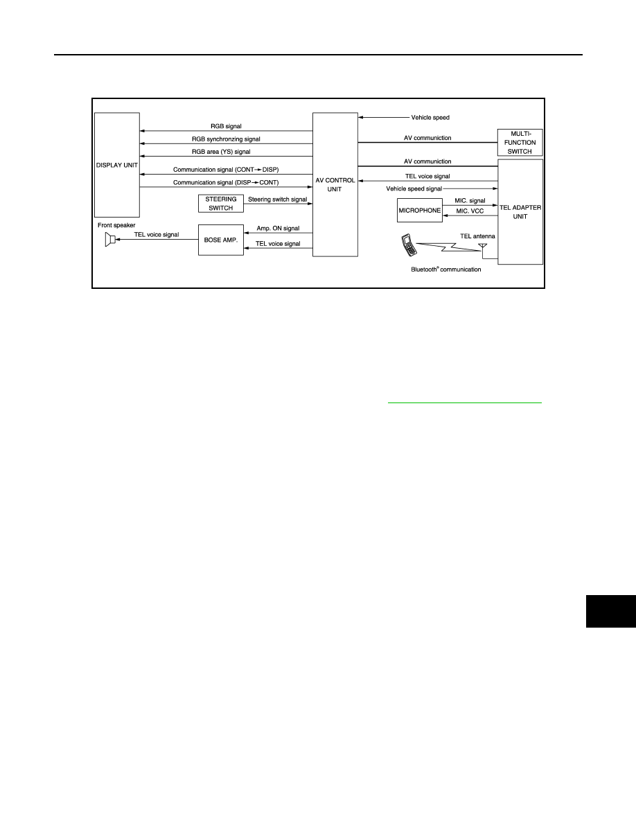
System Diagram
INFOID:0000000003508658
System Description
INFOID:0000000003508659
• TEL adapter unit is controlled with AV communication from AV control unit.
• The connection between portable telephone and TEL adapter unit is performed via Bluetooth
®
communica-
tion.
• The voice guidance signal is input from TEL adapter unit to AV control unit and output via BOSE amp. to
front speaker when operating TEL.
• TEL adapter unit has the on board self-diagnosis function. Refer to
AV-205, "Diagnosis Description"
When receiving a call
TEL voice signal received with the portable telephone is input from TEL antenna via TEL adapter unit to AV
control unit via Bluetooth
®
communication and output via BOSE amp. to front speaker. The operation is per-
formed via steering switch or voice recognition function (TEL operation only).
When a call is transmitted
Voice sound (TEL voice signal) is input from the microphone to TEL adapter unit. It is input from TEL antenna
via Bluetooth communication to portable telephone. It is transmitted to phone on the other side. The operation
is performed with steering switch or voice recognition function (TEL operation only).
JSNIA0701GB