Infiniti EX35. Manual - part 99
AV
MULTI AV SYSTEM
AV-177
< FUNCTION DIAGNOSIS >
[BOSE AUDIO WITHOUT NAVIGATION]
C
D
E
F
G
H
I
J
K
L
M
B
A
O
P
• AV control unit functions by transmitting/receiving data one by one with each unit (slave unit) that configures
them completely as a master unit by connecting between units that configure the MULTI AV system with two
AV communication lines (H, L).
• Two AV communication lines (H, L) adopt a twisted pair line that is resistant to noise.
• AV control unit is connected by CAN communication, and it receives data signals from the ECM, unified
meter and A/C amp. It computes and displays fuel economy information values with the obtained informa-
tion. The transmitting/receiving of data signals is performed by BCM. In addition, it transmits the required
signal of vehicle setting and receives the response signal.
• AV control unit is connected with display and serial communication, and it transmits the required signal of
display and display control and receives the response signal from front display. Also, it is connected with sat-
ellite radio by serial communication, and it transmits the operating signal and receives the display signal.
NOTE:
AV control unit can perform CONSULT-III self-operating function and on board self-diagnosis.
• CONSULT-III self-diagnosis: refer to
AV-201, "CONSULT-III Function (MULTI AV)"
.
• On board self-diagnosis: refer to
AV-192, "Diagnosis Description"
On board self-diagnosis of TEL adapter unit can be performed.
• Refer to
AV-205, "Diagnosis Description"
for on board self-diagnosis.
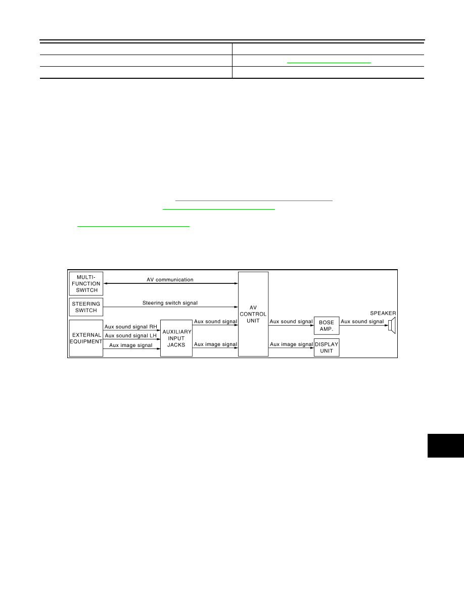
AUXILIARY INPUT SYSTEM
• Image and sound can be output from an external device by connecting a device with auxiliary input jacks.
• Operation can be performed with multifunction switch and steering switch. Multifunction switch transmits
operation signal to AV control unit with communication.
HANDS-FREE PHONE SYSTEM
AUXILIARY INPUT SYSTEM
Refer to “AUXILIARY INPUT SYSTEM” shown below.
System name
System explanation
JSNIA0172GB