Hyundai Tiburon (2003 year). Manual - part 142


  Index      Hyundai     Hyundai Tiburon - service repair manual 2003 year


Search            


Content   ..  140  141  142  143   ..


Hyundai Tiburon (2003 year). Manual - part 142


TIBURON(GK) > 2003 > G 2.7 V6 DOHC > Heating,Ventilation, Air Conditioning > Heater > Temperature 
Control Actuator > Description and Operation, TIBURON(GK) > 2003 > G 2.7 V6 DOHC > 
Heating,Ventilation, Air Conditioning > Heater > Temperature Control Actuator > Description and 
Operation

DESCRIPTION

- Operating temp. : -30°C ~ +80°C 

- Operating voltage : DC 9V ~ 16V 

- Rated voltage : DC 12V 

- Rated load : 4kgf/cm 

- Rated voltage : DC 12V 

- Rated watt. : 0.25W (at 40°C) 

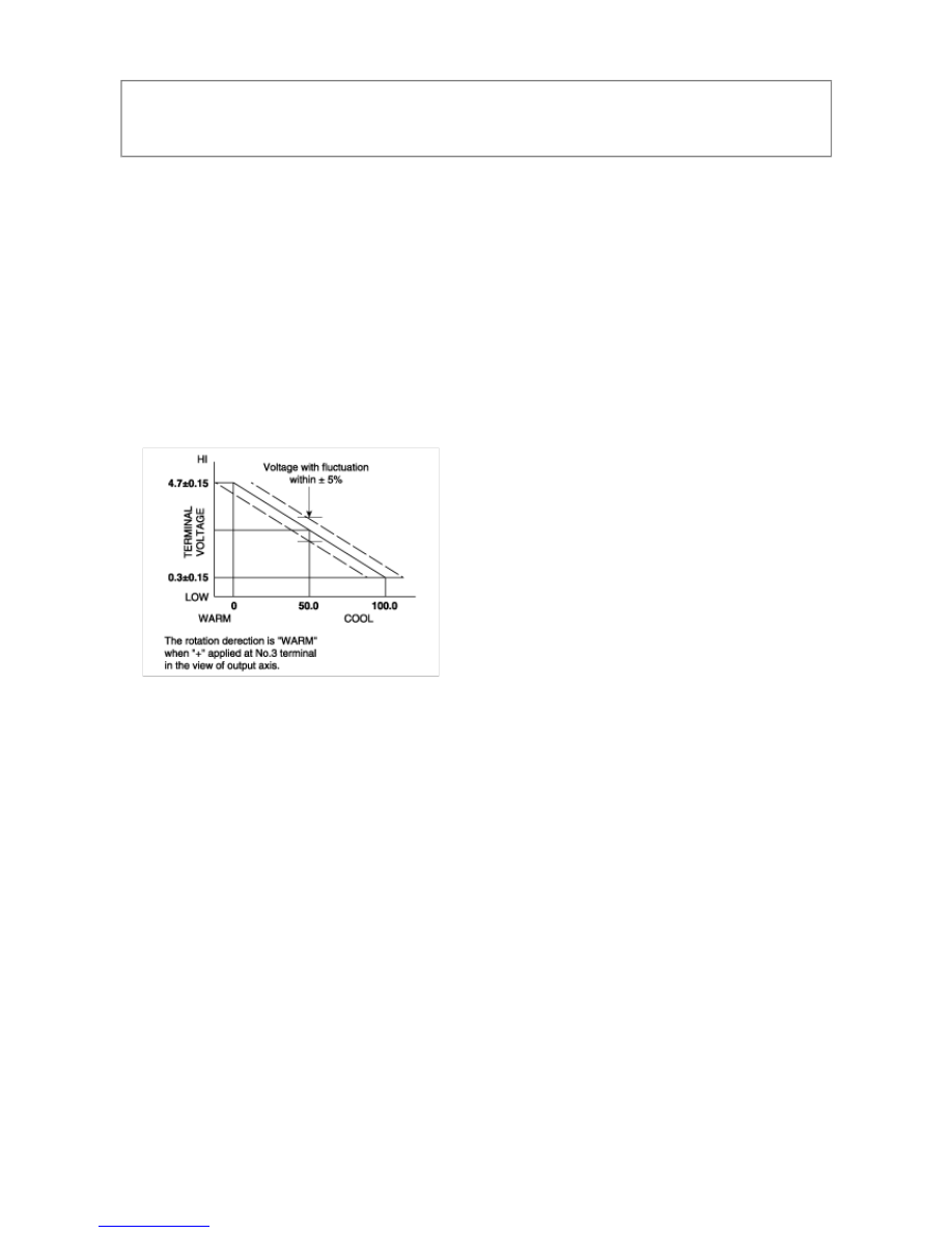
- Opration volt : DC 5V ± 0.5V 

- Total resistance : 5k

 ± 10% 

- Output lock torque : Min 1.76Nm (18kgf/cm) (at DC 12V) 

- Rated AMP : Max. 150mA 

- Lock vol. : Max. 400ma 

- Characteristics 


TIBURON(GK) > 2003 > G 2.7 V6 DOHC > Heating,Ventilation, Air Conditioning > Heater > Temperature Control 
Actuator > Components and Components Location, TIBURON(GK) > 2003 > G 2.7 V6 DOHC > 
Heating,Ventilation, Air Conditioning > Heater > Temperature Control Actuator > Components and Components 
Location

COMPONENT LOCATION


TIBURON(GK) > 2003 > G 2.7 V6 DOHC > Heating,Ventilation, Air Conditioning > Heater > Temperature 
Control Actuator > Repair procedures, TIBURON(GK) > 2003 > G 2.7 V6 DOHC > Heating,Ventilation, Air 
Conditioning > Heater > Temperature Control Actuator > Repair procedures

REPLACEMENT

1. Disconnect the 7P connector (A) from the temp. actuator (B). Remove the self-tapping screws and the temp. 

actuator from the heater unit. 


2. Install in the reverse order of removal. After installation, make sure temp. actuator runs smoothly. 


TIBURON(GK) > 2003 > G 2.7 V6 DOHC > Heating,Ventilation, Air Conditioning > Heater > Mode Control 
Actuator > Schematic Diagrams, TIBURON(GK) > 2003 > G 2.7 V6 DOHC > Heating,Ventilation, Air 
Conditioning > Heater > Mode Control Actuator > Schematic Diagrams

CONNECTOR

Teminal No. 

1 

2 

3 

4 

5 

6 

7 

Mode 

VENT 

DEF 

VCC (+) 

F/B 

SENSOR 

GND (-) 


Content   ..  140  141  142  143   ..