Hyundai Tiburon (2003 year). Manual - part 116


  Index      Hyundai     Hyundai Tiburon - service repair manual 2003 year


Search            


Content   ..  114  115  116  117   ..


Hyundai Tiburon (2003 year). Manual - part 116


TIBURON(GK) > 2003 > G 2.7 V6 DOHC > Clutch System > Clutch System > Clutch Cover And Dinode > 
Repair procedures, TIBURON(GK) > 2003 > G 2.7 V6 DOHC > Clutch System > Clutch System > Clutch 
Cover And Dinode > Repair procedures

REMOVAL

1. Drain the clutch fluid and transaxle gear oil. 

2. Remove the transaxle assembly. 

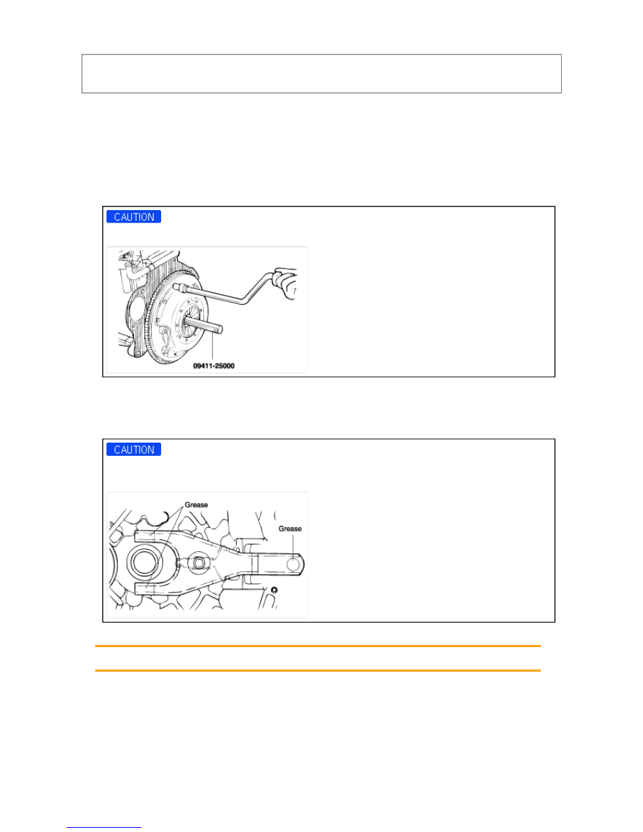
3. Insert the special tool (09411-25000) in the clutch disc to prevent the disc from falling. 

4. Loosen the bolts that attach the clutch cover to the flywheel in a star pattern. 

5. Loosen the bolts in succession, one or two turns at a time, to avoid bending the cover flange. 

DO NOT clean the clutch disc or release bearing with cleaning solvent. 


INSTALLATION

1. Apply multipurpose grease to the release bearing contact surfaces and the release cylinder contact surface of 

the clutch release fork assembly. 

When installing the clutch, apply grease to each part, but be careful not to apply excessive grease. It can 
cause clutchslippage and judder. 


2. Apply multipurpose grease into the groove of the release bearing. 

CASMOLY L9508 


3. Apply multipurpose grease to the clutch release lever fulcrum contact surface of the clutch release fork 

assembly. 


CASMOLY L9508 

4. Clean the surfaces of the flywheel and pressure plate thoroughly with fine sandpaper or crocus cloth, and 

make certain that all oil or grease has been removed. 

5. Apply a small amount of multipurpose grease to the clutch disc splines and input shaft splines. 

CASMOLY L9508 

Do not apply more grease than necessary. Too much grease could cause clutch slip or judder. 

6. Using the special tool (09411-25000), install the clutch disc to the flywheel. When installing the clutch disc, be 

sure that the surface having the manufactures stamp is towards the pressure plate side. 

7. Install the the clutch cover assembly onto the flywheel and install the six (6) bolts through the clutch cover into 

the flywheel. 

8. Tighten the bolts by one or two turns at a time, in succession, to avoid bending the cover flange. 

If a special tool is not available, tighten the bolt temporarily and then torque to specification in diagonal 
torquing sequence indicated below. 


TIGHTENING TORQUE 


Single mass flywheel: 
15~22 N·m (150~220 kg·cm, 11~16 lb·ft) 
Dual mass flywheel: 
20~27 N·m (200~270 kg·cm, 14~19 lb·ft) 

9. Remove the special tool. 

10. Install the transaxle. (Refer to GROUP - Manual Transaxle Assembly) 

11. Adjust the clutch pedal free-play. (See CH-6) 


INSPECTION

CLUTCH COVER ASSEMBLY

1. Check the diaphragm spring end for wear and uneven height. 

Replace if wear is evident or height difference exceeds the limit. 

0.3 mm (0.012 in.) 

2. Check the pressure plate surface for wear, cracks and color change. 

3. Check the rivets for looseness and replace the clutch cover assembly if necessary. 

CLUTCH DISC

1. Check the clutch facing for loose rivets, uneven contact, deterioration due to seizure, adhesion of oil, or 

grease, and replace the clutch disc if defective. 

2. Measure the rivet sink and replace the clutch disc if it is out of specification 

1.1 mm (0.044 in.) 


3. Check for torsion spring play and damage and if defective, replace the clutch disc. 

4. Clean the splines on the input shaft and install the clutch disc. 

If the disc does not slide smoothly or if play is excessive, replace the clutch disc and/or the input shaft. 

CLUTCH RELEASE BEARING

The release bearing is packed with grease. Do not use cleaning solvent or oil. 

1. Check the bearing for seizure, damage or abnormal noise. Also check the diaphragm spring contacting points 

for wear. 

2. Replace the bearing if the release fork contacting points are worn abnormally. 

CLUTCH RELEASE FORK


Content   ..  114  115  116  117   ..