Hyundai Tiburon (2003 year). Manual - part 50
FUEL TANK AND FUEL LINE
Starter motor faulty
Repair starter motor
Starter keeps running
Starter motor faulty
Repair starter motor
Ignition switch faulty
Replace ignition switch
Starter spins but engine will not
crank
Pinion gear teeth broken or starter motor
faulty
Repair starter motor
Ring gear teeth broken
Replace flywheel ring gear or torque
converter
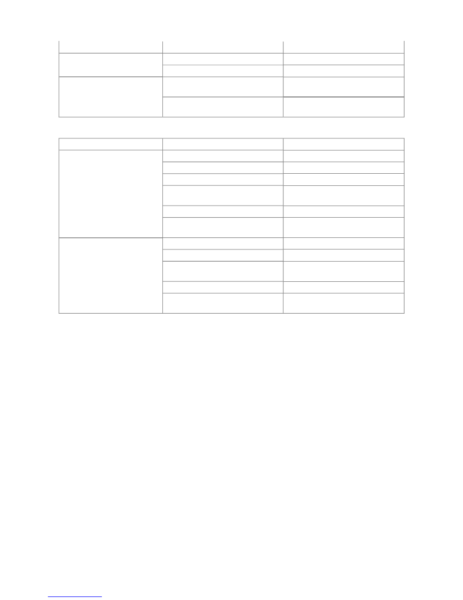
Trouble symptom
Probable cause
Remedy
Engine malfunctions due to
insufficient fuel supply
Bent or kinked fuel pipe or hose
Repair or replace
Clogged fuel pipe or hose
Clean or replace
Clogged fuel filter of in-tank fuel filter
Replace
Water in fuel filter
Replace the fuel filter or clean the fuel
tank and fuel lines
Dirty or rusted fuel tank interior
Clean or replace
Malfunctioning fuel pump
(clogged filter in the pump)
Replace
Evaporative emission system
malfunction (when fuel filler cap is
removed,pressure is released)
Incorrect routing of a vapor line
Correct
Disconnected vapor line
Correct
Folded, bent, cracked or clogged vapor
line
Replace
Faulty fuel tank cap
Replace
Malfunctioning overfill limiter
(two-way valve)
Replace