Hyundai Tiburon (2003 year). Manual - part 31
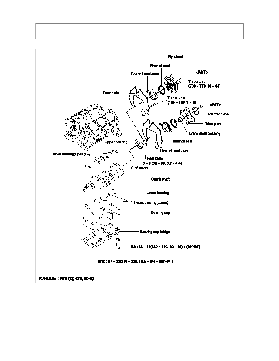
TIBURON(GK) > 2003 > G 2.7 V6 DOHC > Engine Mechanical System > Cylinder Block > Crankshaft >
Components and Components Location, TIBURON(GK) > 2003 > G 2.7 V6 DOHC > Engine Mechanical System >
Cylinder Block > Crankshaft > Components and Components Location
COMPONENTS