Hyundai Tiburon (2003 year). Manual - part 14


  Index      Hyundai     Hyundai Tiburon - service repair manual 2003 year


Search            


Content   ..  12  13  14  15   ..


Hyundai Tiburon (2003 year). Manual - part 14


3. LOAD TEST 

4. Damage and breakage due to heat. 


3. Measure the voltage for the 
battery
 
; Wait at least one day before 
measuring in case of recharging. 

1. 12.0V 


Refer to 
load test 

2. 11.0V< battery voltage<12.0V due 
to over-discharge. 


Refer to 
load test 

3. Below 11.0V due to charge 
condition failure. 


Refer to 
load test 

4. Below 11.0V due to discharged for a 
long period. 


Refer to 
load test 

5. Below 11.0V due to internal short 
circuit. 


Refer to 
load test 

4. Load test 
; For 15 seconds with half of the CCA 
value. 
The voltage on the dischaarging stage 
should be above 9.6V (81±9°F) 

- Conduct the test with a battery 

tester. 
(Refer to the tester manual) 

1. Load test result: below 9.5V 


2. Load test result: above 9.6V 


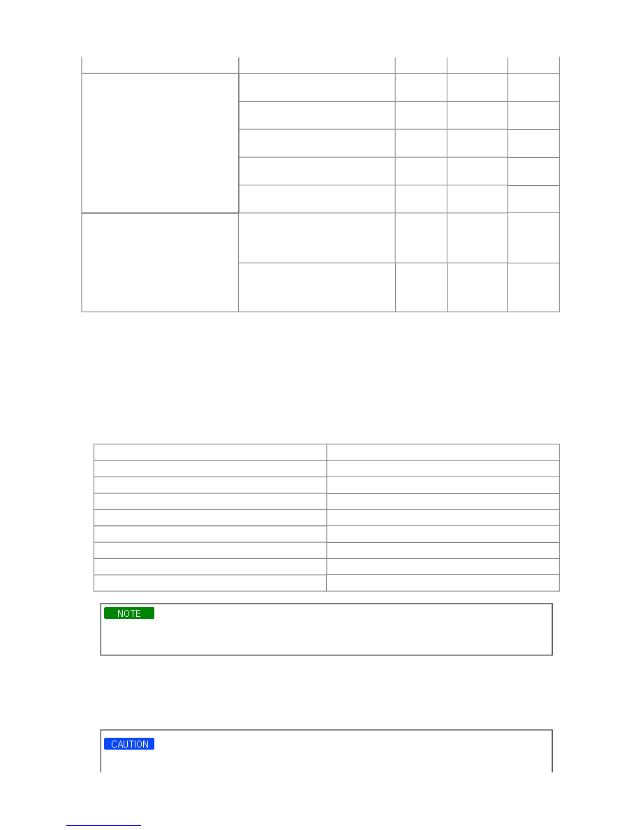
1. Perform the following steps to complete the load test procedure for maintenance free batteries. 

2. Connect the load tester clamps to the terminals and proceed with the test as follow : 


A. If the battery has been on charge, remove the surface charge by connecting a 300 ampere load for 15 seconds. 

B. Connect the voltmeter and apply the specified load. 

C. Read the voltage after the load has been applied for 15 seconds. 

D. Disconnect the load. 

E. Compare the voltage reading with the minimum and replace the battery if battery test voltage is below that shown in 

the voltage table. 

Voltage 

Temperature 

9.6 

20°C (70°F) and above 

9.5 

16 °C (60 °F) 

9.4 

10 °C (50 °F) 

9.3 

4 °C (40 °F) 

9.1 

-1 °C (30 °F) 

8.9 

-7 °C (20 °F) 

8.7 

-12 °C (10 °F) 

8.5 

-18 °C (0 °F) 

- If the voltage is higher than shown in the table, the battery is good. 

- If the voltage is lower than shown in the table, replace the battery. 

BATTERY DIAGNOSTIC TEST (2)

1. Make sure the ignition switch and all accessories are in the OFF position. 

2. Disconnect the battery cables (negative first). 

3. Remove the battery from the vehicle. 

Care should be taken in the event the battery case is cracked or leaking, to protect your skin from the electrolyte. 

Heavy rubber gloves (not the household type) should be worn when removing the battery. 


4. Inspect the battery carrier for damage caused by the loss of electrolyte. If acid damage is present, it will be necessary to 

clean the area with a solution of clean warm water and baking soda. Scrub the area with a stiff brush and wipe off with a 
cloth moistened with baking soda and water. 

5. Clean the top of the battery with the same solution as described in Step(4). 

6. Inspect the battery case and cover for cracks. If cracks are present, the battery must be replaced. 

7. Clean the battery posts with a suitable battery post cleaming tool. 

8. Clean the inside surface of the terminal clamps with a suitable battery cleaning tool. Replace damaged cables and 

broken terminal clamps. 

9. Install the battery in the vehicle. 

10. Connect the cable terminals to the battery post, making sure the tops of the terminals are flush with the tops of the 

posts. 

11. Tighten the terminal nuts securely. 

12. Coat all connections with light mineral grease after tightening. 

When batteries are being charged, an explosive gas forms beneath the cover of each cell. Do not smoke near 
batteries being charged or which have recently been charged. Do not break live circuits at the terminals of 
batteries being charged. A spark will occur when the circuit is broken. Keep open flames away from the battery. 


TIBURON(GK) > 2003 > G 2.7 V6 DOHC > Engine Electrical System > Starting System > Schematic Diagrams, 
TIBURON(GK) > 2003 > G 2.7 V6 DOHC > Engine Electrical System > Starting System > Schematic Diagrams

CIRCUIT DIAGRAM FOR STARTING SYSTEM

The starting system includes the battery, starter motor, solenoid switch, ignition switch, inhibitor switch(A/T), 
ignition lock switch, connection wires and the battery cable. 
When the ignition key is turned to the start position, current flows and energizes the starter motor's solenoid coil. 
The solenoid plunger and clutch shift lever are activated, and the clutch pinion engages the ring gear. 
The contacts close and the starter motor cranks. In order to prevent damage caused by excessive rotation of the 
starter armature when the engine starts, the clutch pinion gear overruns. 


TIBURON(GK) > 2003 > G 2.7 V6 DOHC > Engine Electrical System > Starting System > Description and 
Operation, TIBURON(GK) > 2003 > G 2.7 V6 DOHC > Engine Electrical System > Starting System > 
Description and Operation

DESCRIPTION


Content   ..  12  13  14  15   ..