Hyundai Elantra Neos / Hyundai i30. Manual - part 30


  Index      Hyundai     Hyundai Elantra Neos / Hyundai i30 - service repair manual 2008 year


Search            


Content   ..  28  29  30  31   ..


Hyundai Elantra Neos / Hyundai i30. Manual - part 30


BP-56

BODY  PANEL REPAIR PROCEDURE

REMOVAL

Because the rear floor side members are designed to
absorb energy during a rear collision, care must be
used when deciding to use this repair method. This
repair is recommended only for moderate damage to
the vehicle, where distortions do not extend forward of
the luggage compartment  region. If the damage is
more severe, then the entire side member assembly
should be replaced at the factory seams without
employing this sectioning procedure.

The following procedure applys when only one rear  floor
side member needs to be replaced. If both side
members are damaged and need to be replaced, then
the procedure of  rear floor side members and rear
floor section should be followed.

Refer to the body dimension charts and measure the
vehicle to determine straightening and alignment
requirements.
The body must be returned to its original dimensions
before beginning the repair procedure.
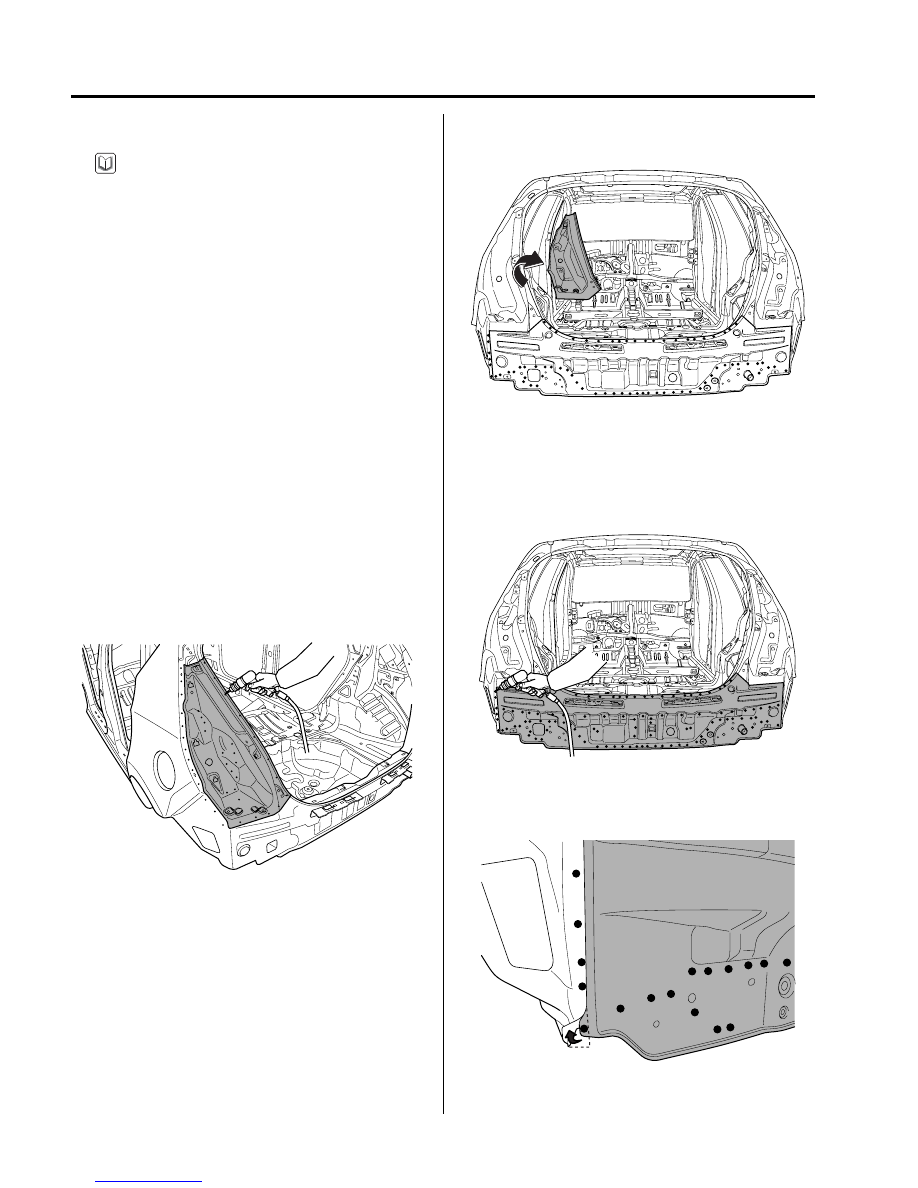
1.

Drill out all the spotwelds attaching the rear combination
lamp housing panel.

2.

Remove the rear combination lamp housing panel.

3.

Drill out all the spotwelds attaching the back complete
panel assembly.

NOTE

BFDBP6701

BFDBP6702

BFDBP6702A

BFDBP6703

BODY PANEL REPAIR PROCEDURE

BP-57

4.

Remove the back complete panel assembly.

5.

Depending on the extent of damage, measure and mark
cutline on the rear floor side member as indicated in
the illustration.

6.

Cut rear floor side member along the cutline.

7.

Drill out all spotwelds and MIG lap welds, attaching
the rear floor side member to rear floor panel.

8.

Remove the rear floor side member.

9.

Clean cut portions with a disc grinder.

BFDBP6704

BFDBP6705A

130mm

BFDBP6705B

BFDBP6706

BFDBP6707

BEDBP6707A

BP-58

BODY  PANEL REPAIR PROCEDURE

10. After removing, apply the welding primer.

11. Prepare all surfaces to be welded.

INSTALLATION

1.

Transcribe the cutline to the new rear floor side member,
adding 30 mm overlap to the rear end.

2.

Drill 8 mm holes in the  new rear floor side member for
MIG plug welding.

3.

Fit and clamp the rear floor side member in place.

4.

Measure each measurement point (Refer to the  BODY
DIMENSIONS) and correct the installation position.

5.

MIG plug weld all holes and MIG lap weld seams.

6.

Clean and prepare all welds, remove all residue.

BEDBP6707B

BFDBP6708

BFDBP6705C

BFDBP6706A

BFDBP6706B

BODY PANEL REPAIR PROCEDURE

BP-59

7.

After removing, apply the welding primer.

8.

Fit and clamp the new back complete panel assembly
in place.

9.

Measure each measurement point (Refer to the  BODY
DIMENSIONS) and correct the installation position.

BFDBP6706C

BFDBP6709

BFDBP6702B

10. MIG plug weld all holes.

11. Clean and prepare all welds, remove all residue.

12. After removing, apply the welding primer.

BFDBP6702C

BFDBP6702D

BFDBP6701A


Content   ..  28  29  30  31   ..