Hummer H1 (1992-1998). Manual - part 32


  Index      Hummer     Hummer H1 - service repair manual 1992-1998 year


Search            


Content   ..  30  31  32  33   ..


Hummer H1 (1992-1998). Manual - part 32


2-32. FUEL INJECTION PUMP REPAIR (Cont’d)

49.

50.
51.

52.

53.

54.
55.

56.

57.
58.

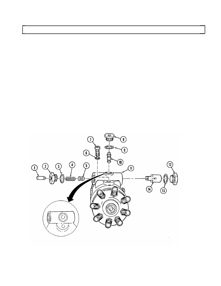
Rotate housing (11) and holding fixture in vise so advance plug (8) faces up.

Install O-ring (6) on head locating screw (7).
Lightly coat head locating screw (7) with seal lubricant and install in housing (11). Tighten screw (7)
to 180-220 lb-in. (20-25 N•m) using 5/16-in. hex head driver.
Install servo advance piston (14) in housing (11) with notch and two small holes facing head locating
screw (7).
Install O-ring (13) and power side advance piston hole plug (12) in housing (11). Tighten plug (12) to
215-265 lb-in. (24-30 N•m).

NOTE

Rotate cam ring to align hole for cam advance pin in housing.

Install cam advance pin (10).
Install O-ring (9) and advance plug (8) in housing (11). Tighten advance plug (8) with 1/4-in. hex

head driver to 75-100 lb-in. (9-11 N•m).

Install servo advance valve (5) on spring (4) and install servo advance valve (5) in servo advance

piston (14).
Install servo advance plunger (1) and O-ring (3) on spring side plug (2).
Install spring side plug assembly (2) in housing (11) so servo advance plunger (1) fits in spring (4).

Tighten sprinig side plug assembly (2) to 215-265 lb-in. (24-30 N•m).

2-116

2-32. FUEL INJECTION PUMP REPAIR (Cont’d)

59. Rotate housing (11) and holding fixture 180°

NOTE

The vent wire screw is available in different sizes (identification
numbers are etched on each) to adjust return oil flow. If original
screw is to be replaced, use the same size. The final determination
will be made during calibration.

60. Install vent wire screw (18). Tighten to 25-30 lb-in. (3 N•m) with 1/8-in. hex head driver.
61. Install metering valve assembly (17) in housing (11).
62. Connect linkage hook (15) to governor arm (20).

63. Install spring (19) on governor arm (20) and linkage hook (15).

CAUTION

Governor arm must be installed correctly or injection pump will
malfunction.

64. Install governor arm (20) in housing (11) so that feet on governor arm (20) fit in slots in thrust

sleeve (21).

65. Install linkage hook (15) on valve arm pin (16).

2-117

2-118

Change 2

2-32. FUEL INJECTION PUMP REPAIR (Cont’d)

N

NO

OT

TE

E

• Perform step 66 for pre-1990 engines.

• Perform step 67 for 6.5L engines and 6.2L engines 1990 and

above.

66.

Install spacer (2) and two O-rings (3) on throttle shaft (1) and install throttle shaft (1) in 
housing (4).

67.

Install spacer (2) and two O-rings (3) on throttle shaft (1). Position governor thrust spring (5) inside
housing (4) and insert throttle shaft (1) through housing (4) and thrust spring (5).

68.

Install mylar washer (6) and face cam (7) on throttle shaft (1) with screw (13). Finger tighten 
screw (13).

69.

Install rocker lever (12) on housing (4) with rocker lever pin (15) and two retaining clips (14).

70.

Put 0.005-in. (0.127 mm) feeler gauge between throttle shaft mylar washer (6) and housing
boss (16).

71.

Put throttle shaft (1) in idle position. Squeeze throttle shaft (1) and face cam (7) tightly toward each
other and rotate face cam (7) so lower roller rests approximately in middle of low idle step. Tighten
screw (13) to 30 lb-in. (3 N

m) with Torx drive and remove feeler gauge.

72.

Align holes in kickdown cam (10) and throttle shaft (1).

73.

Install kickdown cam (10) on throttle shaft (1) with retaining pin (9).

74.

Deleted.

Change 2        2-119

2-32. FUEL INJECTION PUMP REPAIR (Cont’d)

1

2

4

5

6

7

9

10

12

13

14

15

16

3


Content   ..  30  31  32  33   ..