Honda Ridgeline. Manual - part 567
01
SJC8A00K791000R333XFAAT00
−
−
−
−
DTC 33-3x (‘‘x’’ can be 0 thru 9 or A thru F):
Special Tools Required
YES
NO
YES
NO
24-93
B
A
07XAZ-S1A0200
07SAZ-TB4011A
Short to Another Wire or Decreased
Resistance in Left Side Curtain Airbag Inflator
• SRS inflator simulator 07SAZ-TB4011A
• SRS simulator lead E 07XAZ-S1A0200
• SRS simulator lead F 07XAZ-SZ30100
• SRS short canceller 070AZ-SAA0100
NOTE: Before doing this troubleshooting procedure,
review SRS Precautions and Procedures (see page
24-16) and General Troubleshooting Information
(see page 24-27).
1. Clear the DTC memory (see page 24-28).
2. Turn the ignition switch ON (II), and check that the
SRS indicator comes on for about 6 seconds and
then goes off.
Go to step 3.
Intermittent failure, the system is OK at this
time. Go to Troubleshooting Intermittent Failures
(see page 24-29). If another DTC is indicated,
troubleshoot the DTC.
3. Turn the ignition switch OFF. Disconnect the
negative cable from the battery, and wait for 3
minutes.
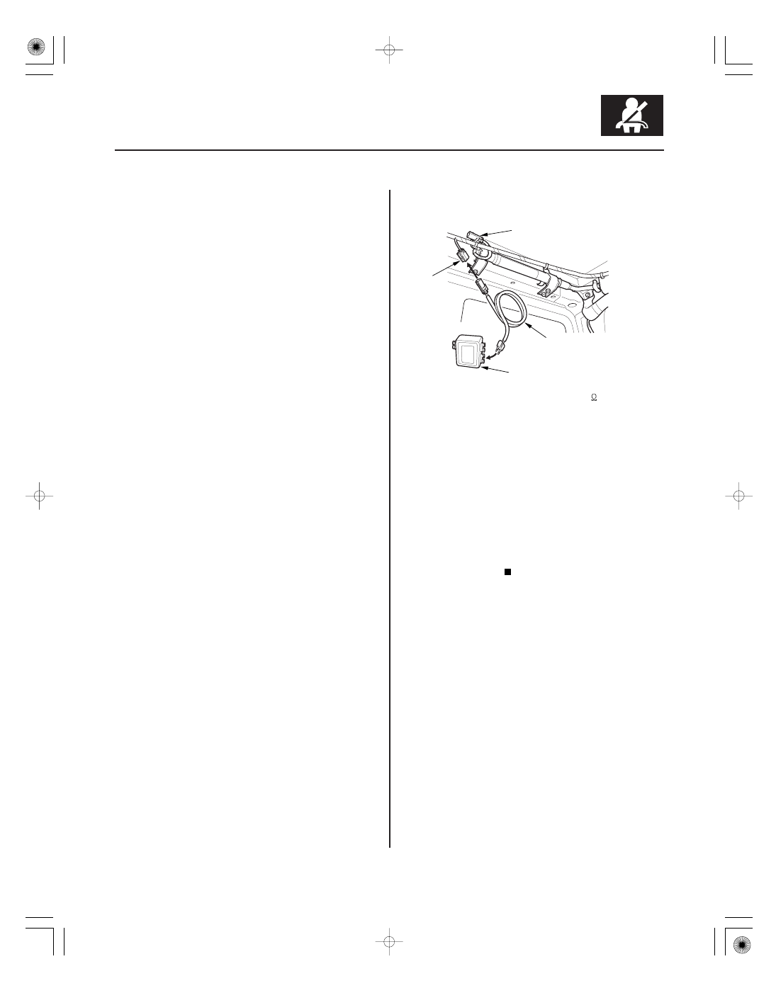
4. Disconnect the roof wire harness 2P connector (A)
from the left side curtain airbag connector (B).
5. Connect the SRS inflator simulator (2
connector)
and simulator lead E to the roof wire harness.
6. Reconnect the negative cable to the battery.
7. Clear the DTC memory.
8. Read the DTC (see page 24-27).
Go to step 9.
Short to another wire in the left side curtain
airbag inflator; replace the left side curtain airbag
(see page 24-177).
9. Turn the ignition switch OFF. Disconnect the
negative cable from the battery, and wait for 3
minutes.
(cont’d)
Does the SRS indicator stay on, and is DT C 33-3x
indicated?
Is DT C 33-3x indicated?