Honda Ridgeline. Manual - part 533
*90
SJC8AN1J36100000000EAAT00
−
+
+
−
−
+
−
−
−
−
+
−
−
−
−
+
−
−
−
−
−
−
−
+
−
23-98
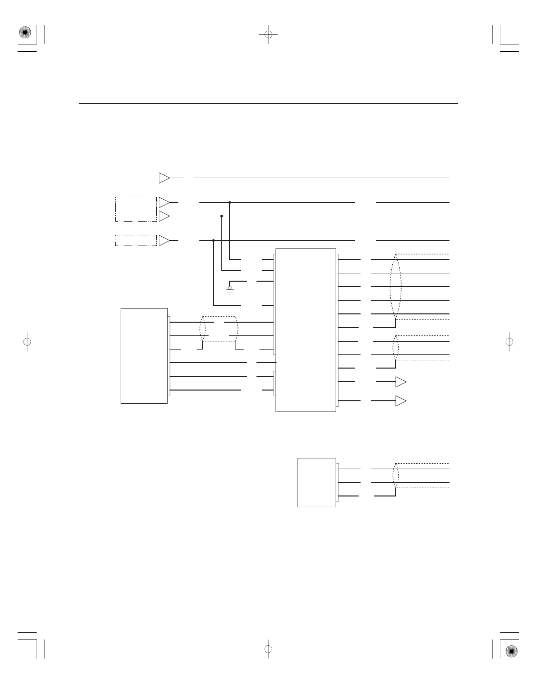
Navigation System
Circuit Diagram
NAVI SCTY 2
DISP OPEN
CD EJECT
A4
A12
A8
B3
B10
B9
LT GRN*
CD CHANGER
MICU
XM RECEIVER
A9
A10
A3
BRN*
BLU
PNK
YEL/RED
WHT/RED
RED/BLK
AUDIO UNIT
RED
GND SIG
A17
NAVI SCTY
ILL
GRN/BLK*
A16
GRN/WHT
A12
A14
PUR
BLU
A20
A15
LT GRN
A5
GRY*
B SIG
C SIG
YEL
A18
BRN
A19
G SIG
A9
RED
A8
R SIG
WHT
CD EJECT
DISP OPEN
NAVI SCTY 2
ILL
GND
B
ACC
NAVIGATION DISPLAY
B9
B10
A4
A6
A11
A3
A13
A10
A1
A2
GRN/RED
GRN
YEL
LT GRN*
BLU/RED
WHT
RED/BLK
G402
BLK
WHT/RED
YEL/RED
RED/BLK
WHT/RED
YEL/RED
GRN
No.4 (15 A) FUSE
No.7 (7.5 A) FUSE
No.32 (7.5 A) FUSE
UNDER DASH
FUSE/RELAY BOX
UNDER HOOD
FUSE/RELAY BOX
AUDIO
BUS
(GA NET)
AUDIO
BUS
(GA NET)
AUDIO BUS
(GA NET)
SHIELD
SIG SHIELD
GND
ECU BUS
(GA NET)
ECU BUS
(GA NET)
ECU BUS
(GA NET)
SHIELD GND
DASHLIGHTS
BRIGHTNESS
CONTROLLER
(In the gauge
control module)
SAT BUS
(GA NET)
SAT BUS
(GA NET)
SAT BUS
(GA NET)
SHIELD
AUDIO BUS
(GA NET)
SHIELD
AUDIO
BUS
(GA NET)
AUDIO
BUS
(GA NET)