Honda Ridgeline. Manual - part 205


  Index      Honda     Honda Ridgeline - service repair manual 2006-2008 year


Search            


Content   ..  203  204  205  206   ..


Honda Ridgeline. Manual - part 205


01

SJC8A00E10410634615KBAT01

01

SJC8A00E10410643821KBAT02

14-205

14-205

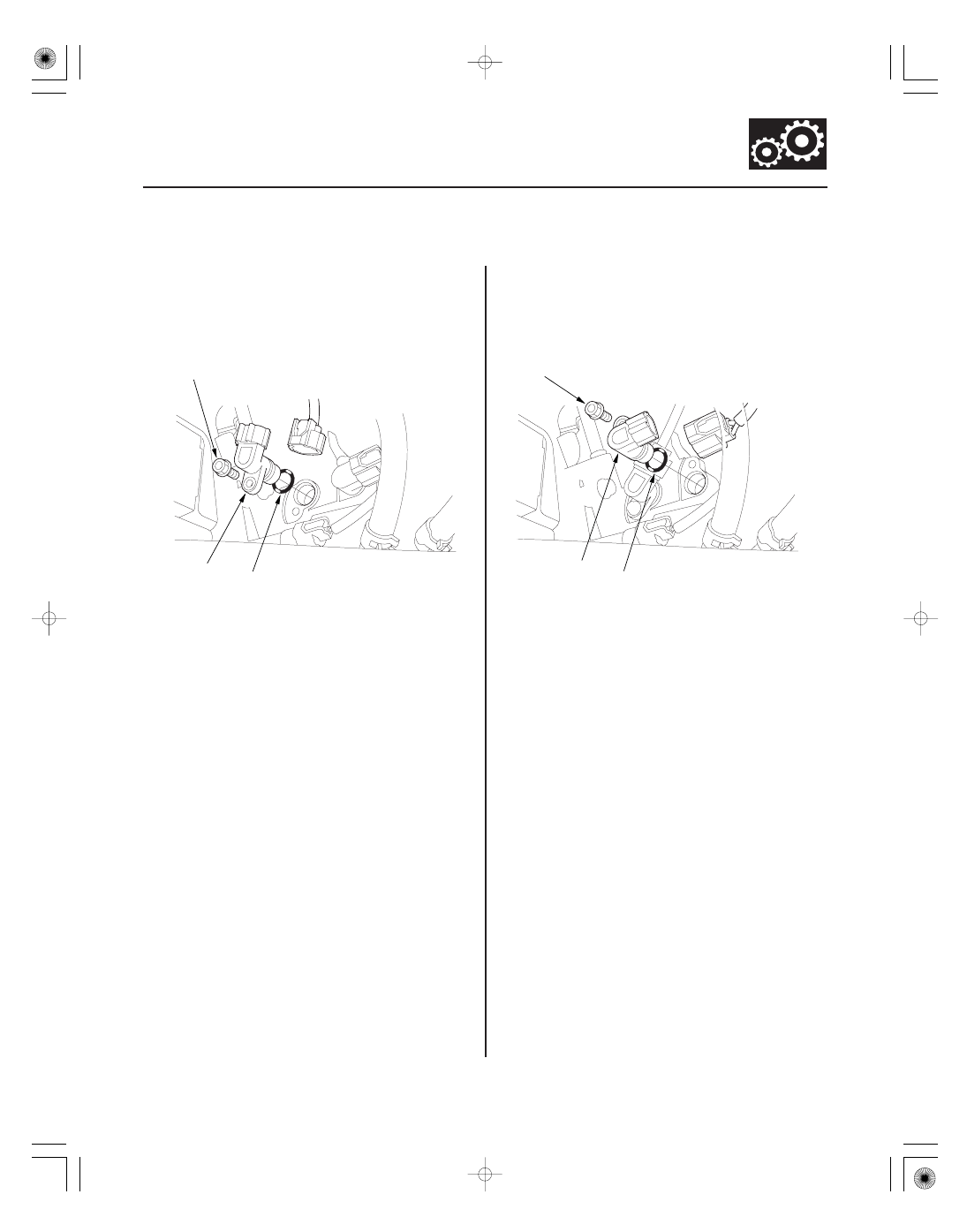
Input Shaft (Mainshaft) Speed
Sensor Replacement

Output Shaft (Countershaft) Speed
Sensor Replacement

6 x 1.0 mm
12 N·m (1.2 kgf·m, 8.7 lbf·ft)

B

A

6 x 1.0 mm
12 N·m (1.2 kgf·m, 8.7 lbf·ft)

B

A

1. Remove the splash shield (see page 20-179).

2. Disconnect the input shaft (mainshaft) speed

sensor connector, and remove the input shaft
(mainshaft) speed sensor (A).

3. Install the new O-ring (B) on the new input shaft

(mainshaft) speed sensor, then install the input
shaft (mainshaft) speed sensor in the transmission
housing.

4. Check the connector for rust, dirt, or oil, then

connect the connector securely.

5. Install the splash shield (see page 20-179).

1. Remove the splash shield (see page 20-179).

2. Disconnect the output shaft (countershaft) speed

sensor connector, and remove the output shaft
(countershaft) speed sensor (A).

3. Install a new O-ring (B) on the new output shaft

(countershaft) speed sensor, then install the output
shaft (countershaft) speed sensor in the
transmission housing.

4. Check the connector for rust, dirt, or oil, then

connect the connector securely.

5. Install the splash shield (see page 20-179).

01

SJC8A00E10410610111KBAT00

14-206

Automatic Transmission

3rd Clutch Transmission Fluid Pressure Switch Replacement

B

A
20 N·m
(2.0 kgf·m, 14 lbf·ft)

1. Remove the splash shield (see page 20-179).

2. Disconnect the 3rd clutch transmission fluid

pressure switch connector, and remove the 3rd
clutch transmission fluid pressure switch (A).

3. Make sure there is no water, oil, dust, or foreign

particles inside the connector.

4. Install a new 3rd clutch transmission fluid pressure

switch and a new sealing washer (B), and tighten
the switch.

5. Connect the connector securely.

6. Install the splash shield (see page 20-179).

01

02

03

SJC8A00E10410610121KBAT00

14-207

4th Clutch Transmission Fluid Pressure Switch Replacement

6 x 1.0 mm
12 N·m (1.2 kgf·m, 8.7 lbf·ft)

A

D

C

B

6 x 1.0 mm
12 N·m
(1.2 kgf·m, 8.7 lbf·ft)

6 x 1.0 mm
12 N·m
(1.2 kgf·m,
8.7 lbf·ft)

B

A

A
20 N·m
(2.0 kgf·m, 14 lbf·ft)

B

1. Remove the intake manifold cover and the intake

air duct.

2. Remove the bolt securing the harness cover (A).

3. Remove the harness clamp (B) from the harness

cover/clamp bracket (C), disconnect the 4th clutch
transmission fluid pressure switch connector (D),
then remove the harness cover from the bracket.

4. Remove the bolts securing the harness cover (A)

and the harness cover/clamp bracket (B).

5. Remove the 4th clutch transmission fluid pressure

switch (A).

6. Make sure there is no water, oil, dust, or foreign

particles inside the connector.

7. Install a new 4th clutch transmission fluid pressure

switch and a new sealing washer (B), and tighten
the switch.

8. Secure the harness cover and harness cover/clamp

bracket with the bolts, and install the harness
clamp on the bracket.

9. Install the harness cover on the cover bracket, and

secure it with the bolt.

10. Connect the connector securely.

11. Install the intake air duct and the intake manifold

cover.

01

SJC8A00E10410613041KBAT00

14-208

Automatic Transmission

ATF Temperature Sensor Replacement

6 x 1.0 mm
12 N·m
(1.2 kgf·m,
8.7 lbf·ft)

F

E

C

A

D

B

1. Remove the splash shield (see page 20-179).

2. Drain the automatic transmission fluid (ATF) (see

step 3 on page 14-210).

3. Disconnect the ATF temperature sensor connector

(A), then remove the connector from the connector
bracket (B).

4. Remove the harness clamp (C) from its bracket (D).

5. Remove the ATF temperature sensor.

6. Install a new O-ring (E) on the new ATF

temperature sensor (F).

7. Install the ATF temperature sensor connector to the

connector bracket, then connect the connector
securely.

8. Install the harness clamp on its bracket.

9. Refill the transmission with the ATF (see step 5 on

page 14-210).

10. Install the splash shield (see page 20-179).


Content   ..  203  204  205  206   ..