Honda Ridgeline. Manual - part 138
01
02
SJC8A00A20336334910KDAT00
01
SJC8A00A20336334791KBAT00
11-316
11-316
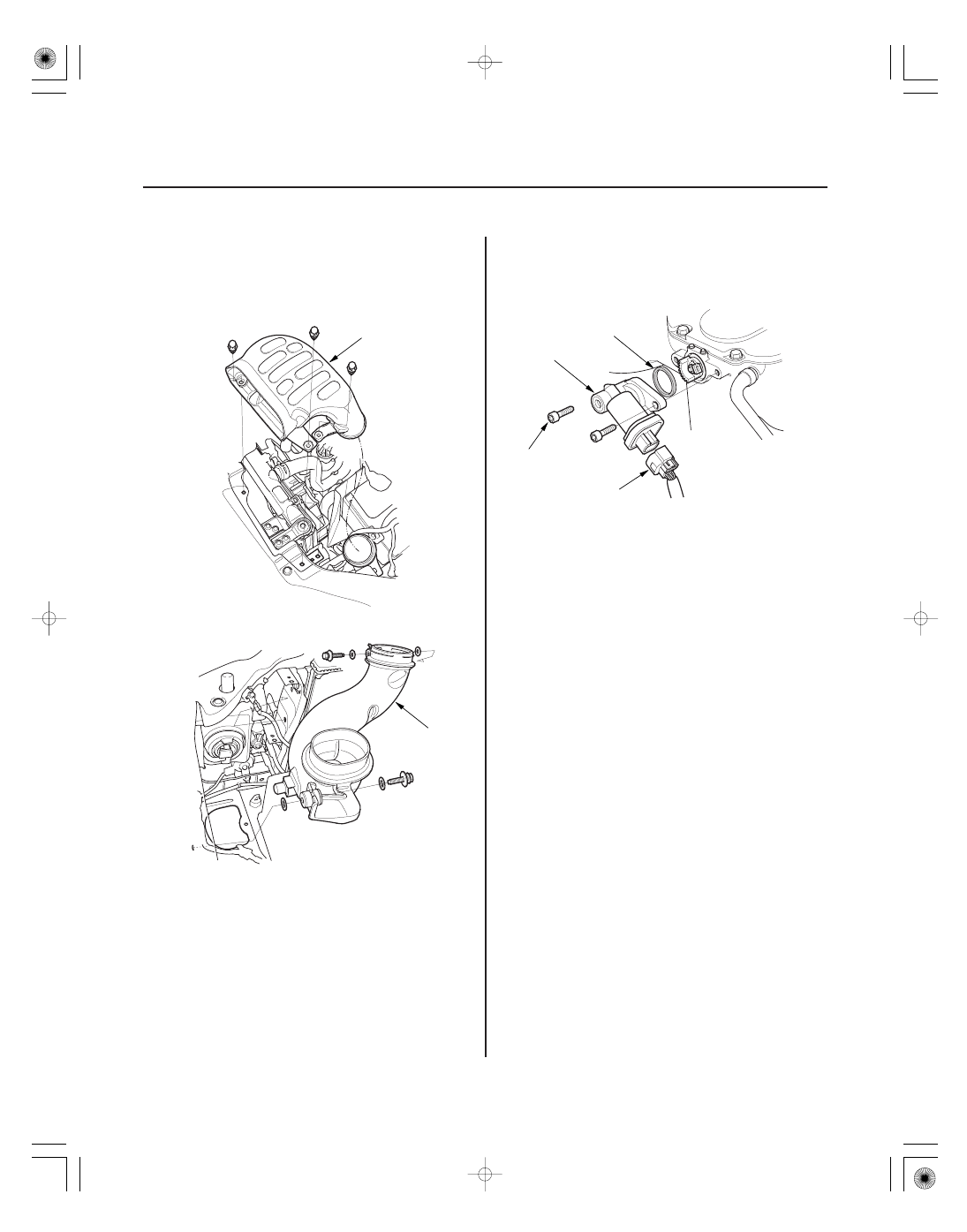
Intake Air System
Air Intake Duct Removal/
Installation
IMT Actuator Replacement
A
A
A
C
D
B
9.8 N·m
(1.0 kgf·m, 7.2 lbf·ft)
1. Remove the air cleaner (see page 11-315).
2. Remove air intake duct B (A).
3. Remove air intake duct A (A).
4. Install the parts in the reverse order of removal.
1. Remove the intake manifold cover (see step 1 on
page 9-3).
2. Disconnect the IMT actuator 5P connector (A).
3. Remove the bolts (B) and the IMT actuator (C).
4. Install the parts in the reverse order of removal
with a new O-ring (D).