Honda Odyssey 2004. Manual - part 577
−
−
−
−
03
*01
05
YES
NO
YES
NO
23-250
SRS
DTC Troubleshooting (cont’d)
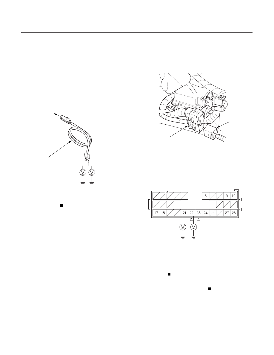
LEFT SIDE WIRE HARNESS
2P CONNECTOR
07XAZ-S1A0200
C852
A
GRN/YEL
GRN
SRS FLOOR HARNESS 28P CONNECTOR
12. Reconnect the battery negative cable.
13. Disconnect the SRS inflator simulator from the SRS
simulator lead E.
14. Turn the ignition switch ON (II).
15. Check for voltage between each terminal of SRS
simulator lead E and body ground. There should be
0.5 V or less.
Faulty SRS unit; replace the SRS unit (see
page 23-384).
Go to step 16.
16. Turn the ignition switch OFF.
17. Disconnect the SRS floor harness 28P connector (A)
from the SRS floor subharness C852.
18. Turn the ignition switch ON (II).
19. Check for voltage between the No. 21 terminal of
the SRS floor harness 28P connector and body
ground, and between the No. 22 terminal and body
ground. There should be 0.5 V or less.
Short to power in the SRS floor subharness
or left side wire harness; replace the faulty
harness.
Short to power in the SRS floor harness;
replace the SRS floor harness.
Terminal side of male terminals
Is the voltage as specif ied?
Is the voltage as specif ied?
03/07/29 10:38:15 61S0X050_230_0250