Honda Odyssey 2004. Manual - part 390
−
−
−
−
−
−
−
−
−
−
*03
*04
*05
YES
NO
YES
NO
YES
NO
YES
NO
YES
NO
21-36
Heating/Air Conditioning
A/C Pressure Switch Circuit Troubleshooting (cont’d)
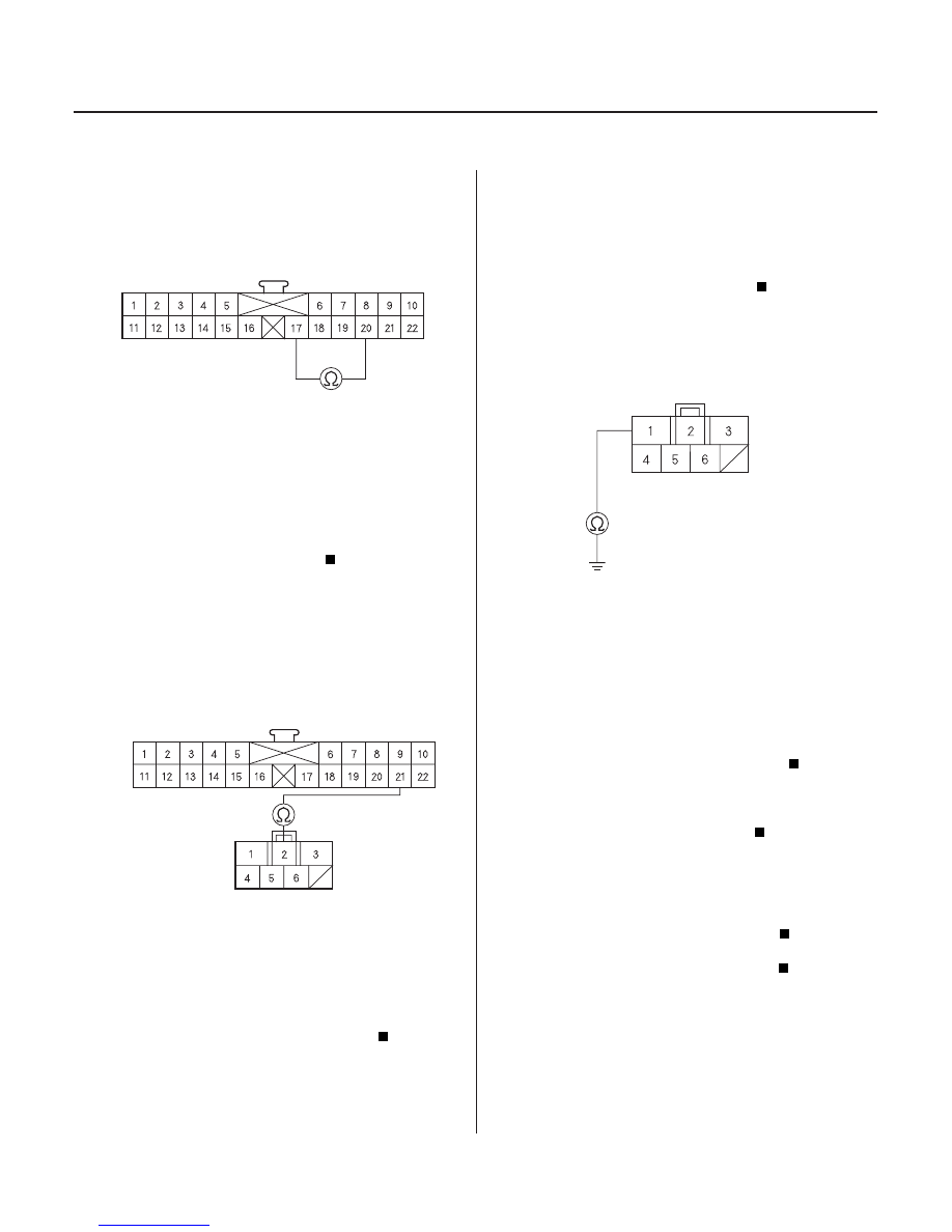
HEATER CONTROL PANEL 22P CONNECTOR
YEL/GRN
BRN
HEATER CONTROL PANEL 22P CONNECTOR
HEATER FAN SWITCH 7P CONNECTOR
GRN
GRN
HEATER FAN SWITCH 7P CONNECTOR
BLK
11. Measure the resistance between the No. 17 and No.20
terminals of the heater control panel 22P connector.
Go to step 12.
Repair cause of high resistance in the
evaporator temperature circuit.
12. Disconnect the heater fan switch 7P connector.
13. Check for continuity between the No. 21 terminal of
the heater control panel 22P connector and the
No. 2 terminal of the heater fan switch 7P
connector.
Go to step 14.
Repair open in the wire between the heater
control panel and the heater fan switch.
14. Test the heater fan switch (see page 21-40).
Go to step 15.
Replace the heater fan switch.
15. Check for continuity between the No. 1 terminal of
the heater fan switch 7P connector and body
ground.
Check for loose wire or poor connections at
the heater control panel 22P connector, the heater
fan switch 7P connector and at the A/C pressure
switch 4P connector. If the connections are good,
substitute a known-good heater control panel, and
recheck. If the symptom/indication goes away,
replace the original heater control panel.
Check for an open in the wire between the
heater fan switch and body ground. If the wire is
OK, check for poor ground at G401.
16. Check for proper A/C system pressure.
Replace the A/C pressure switch.
Repair the A/C pressure problem.
Wire side of female terminals
Wire side of female terminals
Wire side of female terminals
Wire side of female terminals
Is the r esistance less than 24 k ohms?
Is ther e continuity?
Is the heater f an switch OK ?
Is ther e continuity?
Is the pr essur e within specif ications?
03/07/29 10:10:33 61S0X050_210_0037