Honda Odyssey 2004. Manual - part 108
−
−
−
−
−
−
−
−
−
−
−
*01
*02
01
S0X4AZ1K77100090135FAAT00
DTC P0135
’01 Model:
DTC P0141
’01 Model:
YES
NO
YES
NO
YES
NO
YES
NO
11-130
PGM-FI System
DTC Troubleshooting (cont’d)
HO2S 4P CONNECTOR
*
HO2S 4P CONNECTOR
*
PRIMARY/SECONDARY* HO2S (SENSOR 1/
SENSOR 2*) 4P CONNECTOR
IG1
(BLK/YEL)
IG1
(BLK/YEL)
*
PO2S
HTC
(BLK/
WHT)
SO2S
HTC
(BLK/
WHT)*
Primary HO2S
(Sensor 1) Heater Circuit Malfunction
Secondary HO2S
(Sensor 2) Heater Circuit Malfunction
NOTE: Information marked with an asterisk ( ) applies
to DTC P0141.
1. Reset the PCM (see page 11-4).
2. Start the engine.
Go to step 3.
Intermittent failure, system is OK at this time.
Check for poor connections or loose terminals at
the primary HO2S (Sensor 1), the secondary HO2S
(Sensor 2) and the PCM.
3. Turn the ignition switch OFF.
4. Disconnect the HO2S (primary or secondary )
(Sensor 1 or Sensor 2 ) 4P connector.
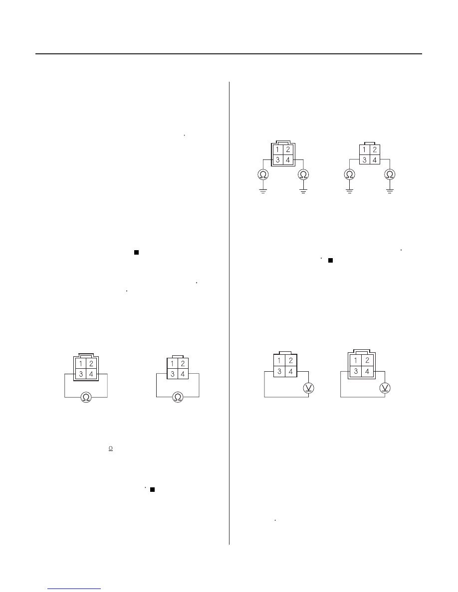
5. At the HO2S side, measure resistance between
HO2S 4P connector terminals No. 3 and No. 4.
Go to step 6.
Replace the primary HO2S (Sensor 1) or
secondary HO2S (Sensor 2) .
6. Check for continuity between body ground and
HO2S 4P connector terminals No. 3 and No. 4
individually.
Replace the HO2S (primary or secondary )
(Sensor 1 or Sensor 2 ).
Go to step 7.
7. Start the engine.
8. Measure voltage between HO2S 4P connector
terminals No. 3 and No. 4.
Go to step 9.
Go to step 12.
9. Turn the ignition switch OFF.
10. Disconnect PCM connector B (24P) (PCM connector
E, 31P) .
Wire side of
female terminals
Terminal side of
male terminals
Wire side of
female terminals
Terminal side of
male terminals
Terminal side of
male terminals
Wire side of
female terminals
Is DT C P0135 or P0141 indicated?
Is ther e 10
40
?
Is ther e continuity?
Is ther e batter y voltage?
03/07/29 09:21:23 61S0X050_110_0130