Honda Element. Manual - part 591


  Index      Honda     Honda Element - service repair manual 2007-2008 year


Search            


Content   ..  589  590  591  592   ..


Honda Element. Manual - part 591


1. Connect the Honda Diagnostic System (HDS) to the data link connector (DLC) (see step 2 on HOW TO 

USE THE HDS (HONDA DIAGNOSTIC SYSTEM) ).  

2. Turn the ignition switch ON (II).  

3. Make sure the HDS communicates with the vehicle and the engine control module (ECM)/powertrain 

control module (PCM). If it doesn't communicate, troubleshoot the DLC circuit (see DLC CIRCUIT 
TROUBLESHOOTING
 ).  

4. Check for DTCs (see GENERAL TROUBLESHOOTING INFORMATION ). If a DTC is present, 

diagnose and repair the cause before continuing with this test.  

5. Start the engine. Hold the engine speed at 3,000 rpm with no load (in the N or P position) until the 

radiator fan comes on, then let it idle.  

6. Check the idle speed (see IDLE SPEED INSPECTION ).  

7. Jump the SCS line with the HDS.  

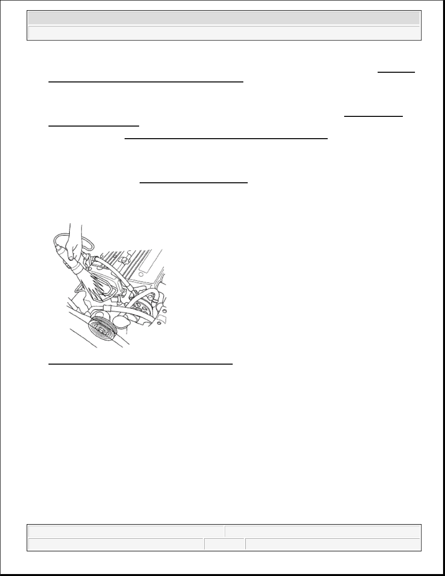
8. Free the service loop from the wire harness, then connect the timing light to the service loop. 

Fig. 3: Connecting Timing Light To Service Loop 
Courtesy of AMERICAN HONDA MOTOR CO., INC. 

9. Aim the light toward the pointer (A) on the cam chain case. Check the ignition timing under a no load 

condition (headlights, blower fan, rear window defogger, and air conditioner are turned off). 

Ignition Tinning  

M/T: 8° ± 2° BTDC (RED mark (B)) at idle in the Neutral  

A/T: 8° ± 2° BTDC (RED mark (B)) at idle in the N or P position


2007 Honda Element EX 

2007-08 ENGINE Ignition System - Element


Fig. 4: Identifying Aim Light Pointer On Cam Chain Case 
Courtesy of AMERICAN HONDA MOTOR CO., INC. 

10. If the ignition timing differs from the specification, check the cam timing. If the cam timing is OK, 

update the ECM/PCM if it does not have the latest software (see UPDATING THE ECM/PCM ), or 
substitute a known-good ECM/PCM (see SUBSTITUTING THE ECM/PCM ), then recheck. If the 
system works properly, and the ECM/PCM was substituted, replace the original ECM/PCM (see 
ECM/PCM REPLACEMENT ).  

11. Disconnect the HDS and the timing light.  

12. Secure the service loop to the wire harness with wire ties.  

IGNITION COIL REMOVAL/INSTALLATION 

1. Remove the ignition coil cover (A), disconnect the ignition coil connectors (B), then remove the ignition 

coils (C). 

Fig. 5: Identifying Ignition Coil Cover And Ignition Coil Connectors With Torque Specifications


2007 Honda Element EX 

2007-08 ENGINE Ignition System - Element


Courtesy of AMERICAN HONDA MOTOR CO., INC.

2. Install the ignition coils in the reverse order of removal.  

IGNITION COIL RELAY CIRCUIT TROUBLESHOOTING 

1. Check the No. 16(15 A) fuse in the under-dash fuse/relay box. 

Is the fuse OK?  

YES - Reinstall the fuse, then go to step 2. 

NO - Replace the fuse. If the fuse continues to blow, locate and repair the short in the circuit between the 
under-dash fuse/relay box and the ignition coils. 

2. Remove the ignition coil relay, and test it (see POWER RELAY TEST ). 

Is the relay OK?  

YES - Go to step 3. 

NO - Replace the ignition coil relay. 

3. Measure the voltage between ignition coil relay 4P socket terminal No. 2 and body ground, then terminal 

No. 4 and body ground. 

Fig. 6: Measuring Voltage Between Ignition Coil Relay 4P Socket Terminal No. 2 And 4 With Body 
Ground
 
Courtesy of AMERICAN HONDA MOTOR CO., INC. 

Is there battery voltage?  

YES - Go to step 4. 

NO - Repair the open in the wire between under-dash fuse/relay box and ignition coil relay.


2007 Honda Element EX 

2007-08 ENGINE Ignition System - Element


4. Check for continuity between ignition coil relay 4P socket terminal No. 1 and each ignition coil 3P 

connector terminal No. 3. 

Fig. 7: Checking Continuity Between Ignition Coil Relay 4P Socket Terminal No. 1 And Body 
Ground
 
Courtesy of AMERICAN HONDA MOTOR CO., INC. 

Is there continuity?  

YES - Go to step 5. 

NO - Repair open in the wire between ignition coil relay 4P socket terminal No. 1 and each ignition coil 
3P connector terminal No. 3. 

5. Check for continuity between each ignition coil 3P connector terminal No. 2 and body ground. 

Fig. 8: Checking Continuity Between Ignition Coil 3P Connector Terminal No. 2 And Body Ground
Courtesy of AMERICAN HONDA MOTOR CO., INC.
 

Is there continuity?  

YES - Go to step 6. 

NO - Repair open in the wire between ignition coil 3P connector terminal No. 2 and body ground.


2007 Honda Element EX 

2007-08 ENGINE Ignition System - Element


Content   ..  589  590  591  592   ..