Great Wall Hover. Manual - part 100
Appendix A-1
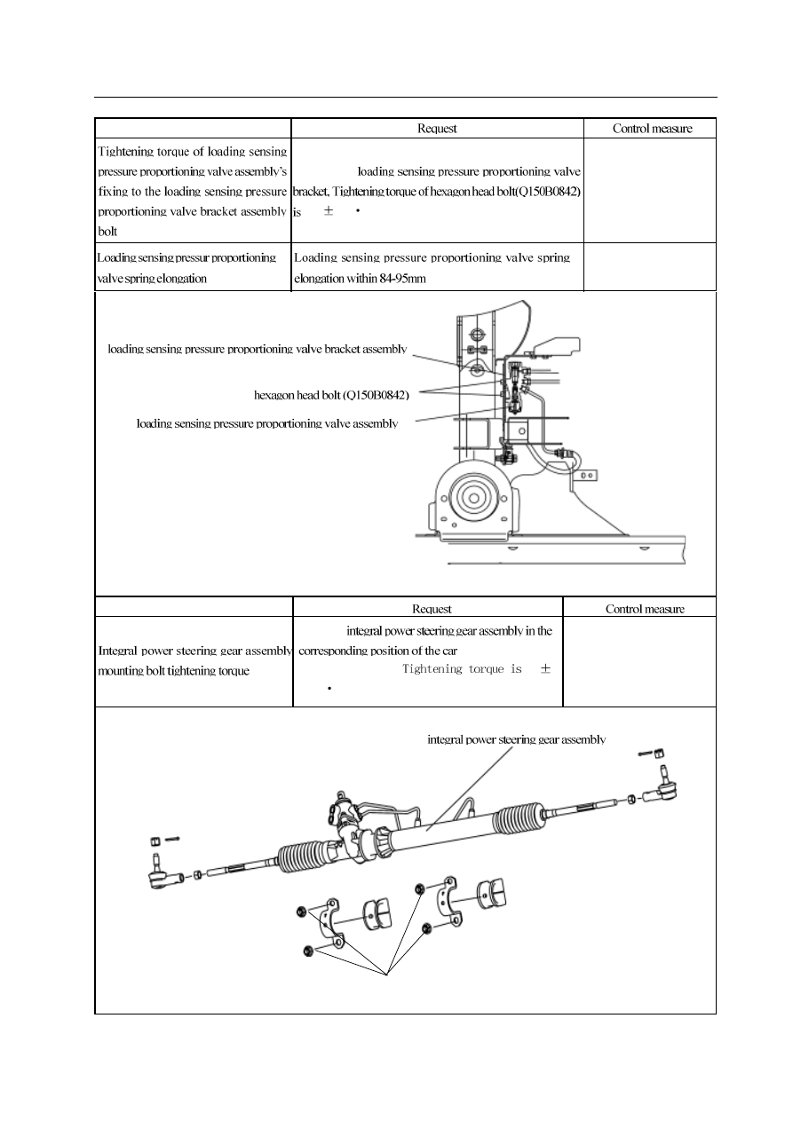
Control item
fixing to the
23
2N
m
Torque wrench
Steel plate gauge 100mm
hexagon flange nut (Q32012)
hexagon flange nut (Q32012)
Control item
locate the
riage and fix it with
some bolts(Q32012),
90
1 0 N
m .
Torque wrench