Great Wall Hover. Manual - part 96


  Index      Great Wall     Great Wall Hover - service repair manual


Search            copyright infringement  


Content   ..  94  95  96  97   ..


Great Wall Hover. Manual - part 96


Safety airbag-21

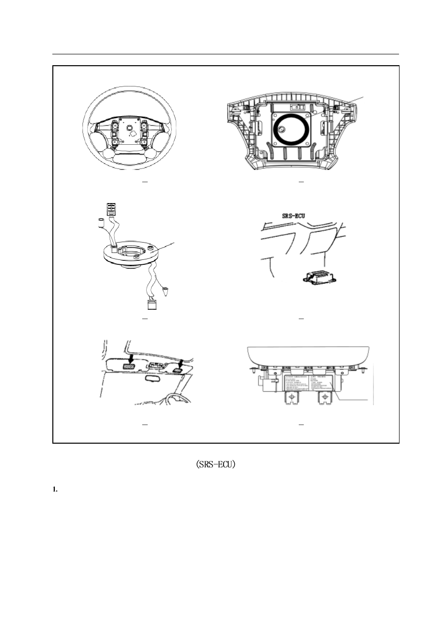
Removal methods for all the parts

Safety airbag electronic-control unit

Caution

  Continue the operation 60 seconds after the removal of accumulator negative. Wrap the removed negative with

insulating tape for insulation.

2. The SRS-ECU must not be separated nor repaired replace the failed SRS-ECU with a new one.

3. Prevent the SRS-ECU from shock and vibration, replace the SRS-ECU with depression, crack or deformation with a

new one.

4. Do replace the SRS-ECU with a new one after the safety airbag is released.

5. Do not damage the SRS-ECU when removing or maintaining the parts next to it.

Figure 6

1

Figure 6

2

Figure 6

3

Figure 6

4

Figure 6

5

Figure 6

6

warning signs

warning signs

passengers’ side safety airbag module

warning signs

Safety airbag-22

1.

Operations before removal

a. Place the ignition switch in OFF position.

b. Remove the accumulator negative and well preserve it somewhere or wrap it with tape.

2.

Removal procedure.

a. Central channel’s side panel (or remove the co-instrument panel)

b. Remove the connector clip connecting with the safety airbag ECU

3.

Installation sequence

a. SRS-ECU;

b. Install the connector clip connecting with the safety airbag ECU

c. Central channel’s side panel (or remove the co instrument panel)

d. Connect the grounding jumper.

4.

Some points for installation

a. SRS-ECU installation

b. Post-installation test

Place the ignition switch in ON position

SRS alarm lamp flashes in 6 seconds and extinguishes.

c. If not extinguishes, the failure test and troubleshooting must be done.

5.

Test

a. Whether the depression, crack or deformation is with the SRS-ECU shield.

b. Whether the terminal is broken or deformed.

Caution: The SRS-ECU safety airbag will not work normally if the SRS-ECU is not correctly installed.

Caution: The SRS-ECU with depression, crack or deformation must be replaced with a new one.

For the inspection of SRS-ECU besides the previous refer to related item of troubleshooting

Safety airbag-23

Driver’s and passengers’ side safety airbag module (DAB, PAB), clock spring

Caution

1. Continue the operation 60 seconds after the removal of accumulator negative. Wrap the negative with insulating

tape for insulation.

2. Safety airbag module and clock spring must not be separated nor repaired, replace the failed ones with new ones.

3. Please pay high attention when using the safety airbag module and clock spring, do not let them fall on the ground

nor fall into water or oil. Moreover, replace the depressed, crack or deformed ones with new ones.

4. After the safety airbag module is released, keep the released side up, store it somewhere flat and do not lay anything

on it.

5. The safety airbag module must not be stored in a place with the temperature above 93

.

6. The released safety airbag module must be replaced with a new one, at the same time test the clock spring, replace

it with a new one if something unusual with it.

7. Use gloves and protection glasses during operating the released safety airbag.

8. The unreleased safety airbag must be abandoned after its release.

Caution

During the removal, the wring harness connector clip must be removed before the removal of other wring harness

connector clips in order to avoid the possible improper release caused by static interferences, which is reversal to the

case of installation.

1. Removal and installation

  Driver’s side safety airbag module, passengers’ side safety airbag module, clock spring.

2. Operations before removal.

a. Take out the ignition switch key after the steering wheel and front wheel in straightforward direction.
b. Remove the connections of accumulator negative

3. Driver’s side safety airbag module removal procedure

a. Screw off the bolts of two sides, as showed in Figure 8-1
b. Shut off the wiring harness connector clip
c. Remove the safety airbag module assembly
d. Remove the steering wheel

4. Passengers’ side safety airbag module removal procedure

a. Remove all the trim covers and glove boxes of instrument panel separate the PAB module’s airbag wiring harness connector

clip from the safety airbag’s PAB side one.

b. Remove M6 bolts and separate PAB module from instrument panel armed beam.
c. Remove the instrument panel itself.
d. Remove the M5bolts of two sides of four PAB modules.

5. Clock spring removal procedure

a. Remove DAB module (shut off the connecting connector clip)
b. Carefully remove the steer
c.  Open the combined switch upper shield, find and shut off the bottom wring harness connector clip
d.  Remove the clock spring from the steer

6. Driver’s side safety airbag module (DAB) and its installation procedure

Safety airbag-24

Figure 8

1

The removal of steering wheel (Figure 8.2)

Figure 8

2

7. Passengers’ side safety airbag module (PAB) and its installation procedure.

a. Test before installation

Carefully take PAB module, justify both of them and plug four trim cover M5bolt into the mounting holes of the module’s
both sides
Well install together the module with trim cover bracket and instrument panel mounting bracket with four M5 bolts.
After the installation of the entire instrument assembly to the vehicle, tightly fix the PAB module to the vehicle transverse
beam with 2 matted M6 bolts at the glove box site.
Well mutually plug the PAB module airbag wiring harness connector clip and safety airbag wiring harness  PAB side
connector clip it is the end of PAB module installation.

b. Connection of accumulator terminal
c. Post-installation test

8. Clock spring installation procedure

a. Test before installation

Cross the line of upper clock spring through the hole in steer.
connect and fix the clock spring and steer
install the combined switch upper cover
install the steering wheel
steering wheel and safety module assembly

b. Connect accumulator’s terminal
c. Post-installation test


Content   ..  94  95  96  97   ..