Great Wall Hover. Manual - part 67


  Index      Great Wall     Great Wall Hover - service repair manual


Search            copyright infringement  


Content   ..  65  66  67  68   ..


Great Wall Hover. Manual - part 67


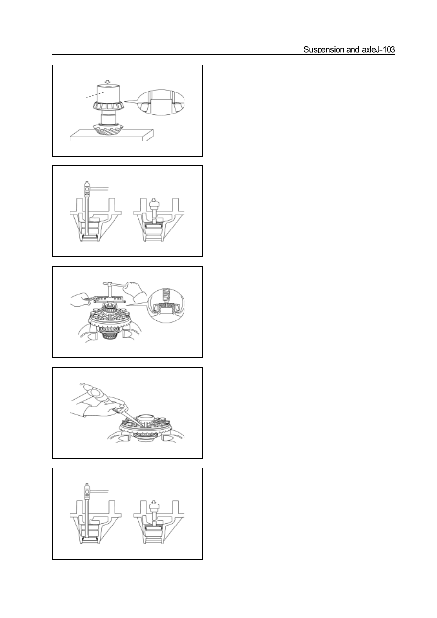
b.Use the press machine and special tools to install the reused

   adjusting washer and new rear bearing on the drive bevel gear.

12. Replacement of front and rear bearing outer race

      of drive bevel gear.

a. Use the hammer and brass bar to knock out the front and rear

    bearing.

b. Use the press machine and special tools to install the new

    bearing outer race by press.

13. Remove the side bearing form the differential

     housing.

Use the special tools to pull out the side bearing from the differ

ential housing.

14. Remove the driven bevel gear

a.Remove the connecting bolt and lock plate of driven bevel gear.

b.Make the assembly mark on the driven bevel gear and differen

    tial housing.

c.Use the rubber hammer or brass rod to knock down the driven

   bevel gear.

Assembly of reducer

1. Install the bearing outer race of drive bevel gear.

(Refer to Step 12 in “Disassembly of Reducer”)

special tools

2. Install the rear bearing of drive bevel gear and ad

    justing washer

a. Select the proper adjusting washer according to “Meshing Condi

    tion of Drive Bevel Gear and Driven Bevel Gear”.

b. Install the rear bearing and selected adjusting washer by press

    machine.

3. Install the spacer.

a.Select the adjusting washer between the rear bearing and spacer

   based on the experience.

b.Install the spacer.

4. Install the front bearing inner race, oil baffle disc

    and oil seal of drive bevel gear

a. Place the front bearing inner race in the reducer housing; place the

    oil baffle disc.

b. Coat the position of reducer housing oil seal and lip of  oilseal

    with grease uniformly; place the oil seal in position. Start the

    press machine for installation.

5. Install the drive bevel gear, flange and dustproof

    cover assembly

a. Install the flange and dustproof cover assembly in the reducer

    housing, Press it to level by hand.

b. Insert the drive bevel gear installed with the spacer, rear bearing

    and adjusting washer into the flange through the spline; screw on

    the nut.

c. Use the nut to tighten the flange, plain washer and drive gear.

special tools

level

special tools

6 Use the special tools to clamp the flange; use the

    torque wrench to tighten the nut.

Tightening force:   140

160N

m

7. Measure the rotation pretightening force of bearing

For new bearing  :   1.2

1.7N

m

For reused bearing  :   0.4

0.6N

m

If does not meet the requirement, replace the adjusting washer

under the spacer until meet the requirement.

Tightening torque :   0-3.5N

m

a. Reduce the thickness of adjusting washer if the measured value

    is less than standard value;

b. Increase the thickness of adjusting washer if the measured value

    is more than standard value.

8. Install the driven bevel gear on the differential

    housing.

a. Use the bolt and lock plate to connect the driven bevel gear to the

    differential housing.

b. Screw on for three rounds at least by hand; then use the pneu

         matic wrench to tighten it properly.

c. Use the torque wrench to tighten it.

Tightening force:   65-95N

m

Caution: Tighten the bolt in diagonal .

Use the hand hammer and flat head punch to lock the lock plate.

Special tools

9. Install the differential side bearing by press.

Use the press machine and special tools to install the side bearing

on the differential housing by press.

10. Install the differential assembly

a.Remove the bearing gland. Do not mix the left up with right.

b.Install the differential assembly in the reducer housing.

11.Install the adjusting ring

Use the adjusting ring to press the bearing outer race in position;

tighten it properly. Adjust the clearance between the drive and

driven gear to the proper dimension.

12. Install the bearing gland

a. Align the assembly mark on the bearing cover with that on re

   ducer housing; Press down the press cover by hand.

b. Install the lock washer with double ears and nut; tighten the

    hexagon nut by pneumatic wrench properly.

13. Adjust the engagement clearance between the drive

     and driven gear.

a. Use the torque wrench to tighten four bolts on bearing cover by

    torque wrench.

Tightening force:   78-115N

m

special tools

special tools

assembly mark


Content   ..  65  66  67  68   ..