Great Wall Hover. Manual - part 45


  Index      Great Wall     Great Wall Hover - service repair manual


Search            copyright infringement  


Content   ..  43  44  45  46   ..


Great Wall Hover. Manual - part 45


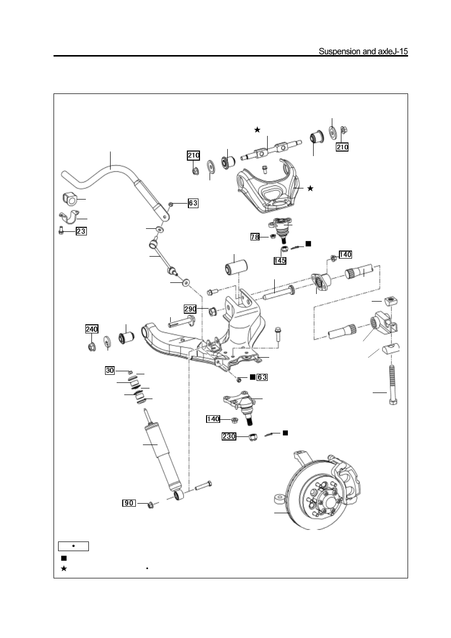
Front suspension (2WD)

front stabilizer bar

rubber cover

clip

connecting rod of

stabilizer bar

flat shim

front shaft of

lower arm

split pin

adjusting bolt

lower adjusting block

fixed arm

upper adjusting block

lower arm

rear shaft of lower arm

torsion bar base

torsion bar

lower arm long bush

split pin

upper ball pin

upper arm shaft

upper arm bush

flat shim

lower arm

short bush

eccentric shim

disk shim

fill block

fill block

disk shim

shim

shock absorber

shim

shim

upper arm bush

upper arm shaft

lower ball arm

front wheel hub

and steering

knuckle assy

N  m:  specified torque

Used component which can not be used any more.

Pregummed component N 

m: specified torque

Ball pin

Inspection of ball pin

1. Check the lower ball pin for loose

a.   Raise the front of the car by jack and support it by the frame.

b. Ensure the front wheel is in straight advancing position and

step down the brake pedal.

c. Move the arm upwardly and downwardly; check the

clearance of lower ball pin.

 Max. vertical clearance: 0mm

2. Check the upper ball pin for loose;

move the wheel upwardly and downwardly and check the gap of

upper ball pin.

Max. vertical clearance: 0mm

3. Check the rotation of ball pin

a. Remove the ball pin.

b.   Shown as figure, shake the ball pin stud forwardly and

backwardly for several times before install the nut.

     c.   Rotate the nut continuously by torsion meter and 2-4s for a

  cycle; record the readout of torsion meter in the fifth cycle.

  tightening torque (for rotary):

  lower ball pin   0.1

4N

m

  upper ball pin   0.1

4N

m

Disassembly of ball pin

1.Take down the steering knuckle and front wheel hub assy.

Installation of ball pin

1. Install the upper ball pin on the upper arm

Tightening force: 78

5N

m

2. Install the lower ball pin on the lower arm

Tightening force: 140

10N

m

3. Install the steering knuckle and front hub assembly

    (Refer to section Front Hub and Steering Knuckle)

Disassembly of ball pin

(Refer to section “Front Hub and Steering Knuckle”)

2. Remove the lower ball pin form the lower arm

3. Remove the upper ball pin from the upper arm.

Torsion bar spring

Disassembly of torsion bar spring

Installation of torsion bar spring

Caution: There are the L and R indication marks, which must

not be exchanged on the read end of the torsion bar spring.

Mark L means the left andRforright

.

1. For reused torsion bar spring

a. Coat thin grease on the spline of torsion bar spring.

b. Align the assembly mark, install the torsion bar spring on the

torsion bar.

 c.   Align the assembly mark; install the adjusting arm onthtorsion

  bar spring.


Content   ..  43  44  45  46   ..