Great Wall Hover. Manual - part 32


  Index      Great Wall     Great Wall Hover - service repair manual


Search            copyright infringement  


Content   ..  30  31  32  33   ..


Great Wall Hover. Manual - part 32


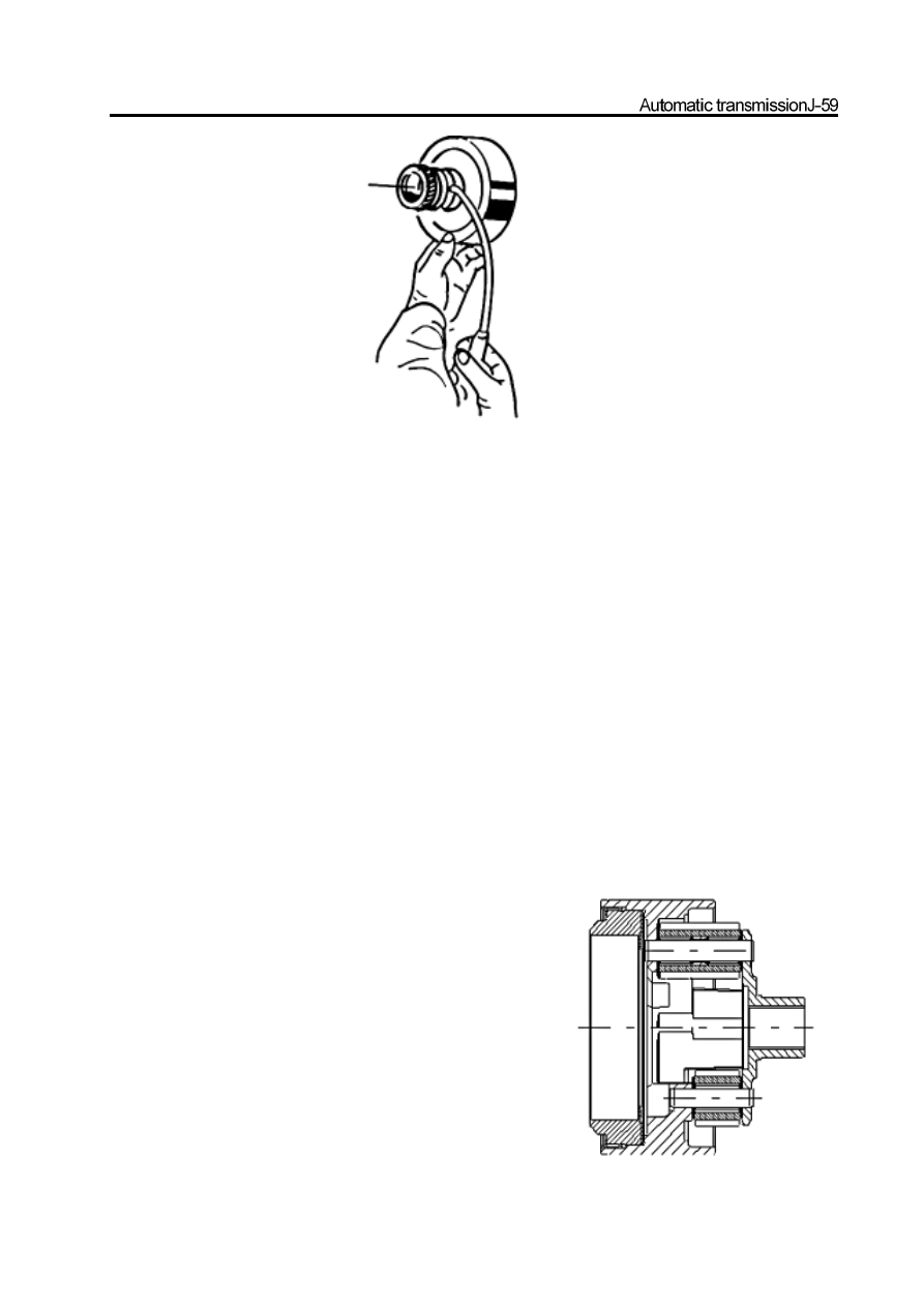
Figure 8.8   Removal of clutch C3 piston

     c.    Install the clutch assembly on the special tools, press down the piston out-back spring; take out the retainer and release spring.

Caution:

Ensure the spring keeping device does not be clamped in the spring groove and all spring pressure is released.

d. Take out the tools, retainer, retainer and spring.

e. Take out the gasket from the clutch C3 cylinder.

f. Take out the clutch disk fixed spring ring and take out the clutch disk.

g. Send the compressed air into the hole between the iron sealing ring and support shaft neck of cylinder; remove the clutch piston

from the clutch cylinder. Refer to Figure 8.8.

h.  Take out the cylinder forms the reverse sun gear and C3 washer.

5. Planet carrier and central support

The disassembly procedure of planet carrier and central support, the procedure is shown as follows:

a. Separate the planet carrier and central support from the output shaft; remove the thrust bearing and planet carrier form the

output shaft.

b. Rotate the planet carrier in anticlockwise and separate the central bracket.

c.   Raise the one-way clutch form the planet carrier

d. Remove the spring ring on the planet carrier; maintain the periphery of one-way clutch on the planet carrier and take it out.

Refer to Figure 8.9.

 e.   Remove the one-way clutch fixed mount form the planet carrier.

Figure 8.9  Planet carrier and external race way

6. Pump

Cautions: the following valves are installed in the pump cover:

solenoid valve 7

C1 eccentric valve ( only for early stage mode, no valve in M88)

torque converter control valve

torque converter regulating valve

primary regulating valve

The disassembly procedure of pump is shown as follows:

a. Remove the wire bunch fixing disc and use the special tools T30 to remove the solenoid valve 7.

b. Use the 8mm sleeve to remove 5 bolts and washers.

c. Use the tool NO.30 to remove 5 screws form the cover plate. It should notice that the odd number screw has the function of

connecting the pump body to the pump cover plate.

Caution:

Do not release the pump by the method of knocking the torque converter support.

d. Separate the pump body from the pump cover.

e. Lift the pump cover disc form the pump cover.

f. Remove two ball spool detection valves and a spring from the pump cover.

Caution:

Some valves and plugs are connected by the spring and may fall down form the housing when remove the pin.

g. Press down the socket inwardly to remove the fixed pin of 4 valves.

h. Take out 4 valves, plugs and springs.

i.

Take out the pump gear form the gear.

j. Remove the edge sealing from front of pump when replace it.

7. Valve

The removal procedure of valve is shown as follows:

a. Use the special tools T40 T orxbit to remove the ratchet spring and retainer plate.

Caution:

The manual-operated valve may fall down form the valve.

b. Slide the manual-operated valve to out of lower valve.

c. Pay attention to the angle relationship between the electromagnetic end and valve, remove the solenoid valve and valve

assembly according to the following procedure :

Solenoid valve 1

Solenoid valve 2

Solenoid valve 3

Solenoid valve 4

Solenoid valve 5

Solenoid valve 6

d.  Place the valve on the platform with the top upwardly.

e.  Use the model NO.30 Special tools to remove the 24 fixing screw. Lift the upper valve and separating disk to separate the

upper valve form the lower valve

f. Reverse the upper part, place the separating disk on the platform upwardly.

g. Lift the separating disk and washer from the upper valve.

h. Remove 5 exposed nylon detection ball spools of valve.

i.

Remove the locking nut disc, spring and reverse lock valve.

j.

Remove two cleaners  (and large nylon detection ball spool ) from the lower valve.

Caution:

Once the pin is removed, the disc in the valve may be loose and slid form the valve when reverse the valve.

k. Remove the locking nut disc and bolt form 1-2, 2-3, 3-4, BAR,CAR valve; the bolt can be removed by the bolt.

l.

Remove the 1-2, 2-3 and 3-4 shift valve.

Caution:

Some valves are pulled by the spring and may fall down form the valve.

m.  Press down the plug of 4-3 sequence valve and take out the locking nut disc.

n. Take out the plug, valve and spring.

o. Press down the solenoid valve 5 gate. Remove the fixed pin, valve and spring.

Caution:

The valve is pulled by the spring and may fall down form the valve.

p. Press down the line pressure blow-off valve , then remove the fixed pin, disc (if proper) spring and valve.

q. Take out the roller pin and remove the spring and ball spool detection valve adjacent BAR.

Assembly

The transmission is assembled in the method of module. The detailed assembly process of each module is described in the

following chapter in detail.

Refer to Table 8.1 (end of section 8.3) for the description of used torque specification. The Table 9.10 in section 9.6 describes

the necessary special tools for assembly.

The technician also needs to select the quality Torx tools, especially for the two-screw socket wrench with code of 40, 50,

8mm,10mm and 12mm to detect the transmission completely.

1.Transmission

Caution:

Ensure the BIR retainer is proper for the case (otherwise, the valve will damage the separation disk).

Ensure the E clip is installed on the cross shaft.

Ensure all parts of parking machine can operate normally.

The assembly procedure of transmission is shown as follows:

a.

Place the upper transmission on the platform upwardly and place it on the transmission bracket.

b.

Install all accessories, bolts and bleed devices. Paint the sealant on the sealing place. Tighten all components according

to the specification. Ensure the cleanness of all bleed devices. Ensure the rear oil filling nozzle of housing is correct and

without blocking material. Refer to Figure 8.19.

c.

Assemble the BIR valve and spring; ensure the retainer is installed correctly, refer to Figure 

 8.10. Ensure the

retainer is fixed in the groove completely.

  d.    Install the rear servo bar and pin shaft. Refer to Figure 8.11.

Caution: Ensure the crown bar can rotates freely.

Figure 8.11  Rear servo bar

Caution:

Pay attention to do not coat the sealant between the bolt and crown bar.

e.   Install the parking operating lever (as Figure 8.12), including the return spring and shaft pin. Coat the external end of shaft pin

with small sealant.

f. Use the circlip to protect the shaft pin. Pay attention to ensure the operating lever can rotate around the shaft pin freely and

the spring can make the parking operating lever returns to the correct position.

g. Install the parking brake lever pin and spring. Refer to Figure 8.13.Caution:  ensure the rake lever can rotate freely.

h. Connect the parking brake lever to the manual-operated valve connecting rod. Shown as Figure 8.14. Ensure the spring and cam

axle ring are installed on the connecting rod fixedly.

i.

Check the cam axle ring for smooth sliding on rod.

j.

Install the cross shaft in the box in reverse direction of Gear-position sensor, then install the concussion spring on the shaft.

Figure 8.12   Parking operating lever

Figure 8.13  Typical parking brake shaft pin and spring

Figure 8.14   Parking lever and manual shaft


Content   ..  30  31  32  33   ..