Great Wall Hover. Manual - part 17


  Index      Great Wall     Great Wall Hover - service repair manual


Search            copyright infringement  


Content   ..  15  16  17  18   ..


Great Wall Hover. Manual - part 17


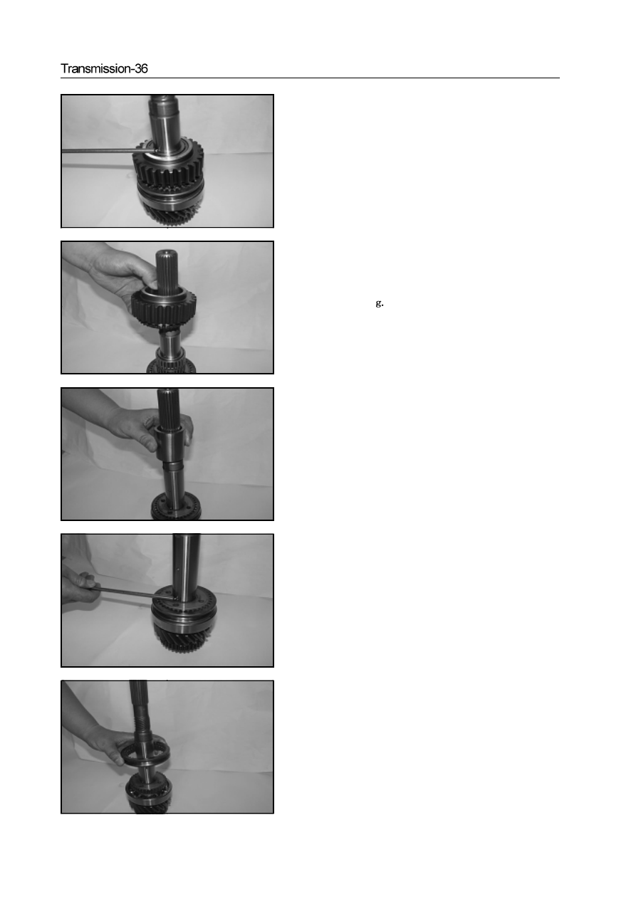
e. Use the magnetic rod to remove the steel ball.

f. Remove the drive sprocket and needle bearing

Caution: When install the drive sprocket, it should use the plug

gage to measure the drive sprocket axial clearance and ensure

within 0.19-0.338mm

g  Remove the drive geared sleeve

h. Use the magnetic rod to remove the steel ball.

i.  Dismantle the drive gear sleeve.

Transmission-37

j

Remove the gear hub

k

Remove the spacing plate

l. Use the circlip pliers to remove the circlip.

Caution: It should select the circlip for shaft according the angle

when install it.

m.Remove the high and low geared sleeve and gear hub

n. Remove the low-speed driven gear, needle bearing and rear output

shaft

Caution:  When install the low-speed driven gear, it should use the

plug gage to measure the axial clearance of low-speed driven gear

axial clearance to ensure the axial clearance is 0.17-0.284 mm

Mark

Thickness (mm)

White

Blue

Green

Automatic transmission-1

   Chapter 5

   Automatic transmission  (M88)

Instruction for automatic transmission .........................................2

Operation and display interface ..................................................5

Control system...........................................................................7

Power transmission system..........................................................22

Power transmission ...................................................................26

Diagnosis and test.......................................................................45

Adjustment................................................................................53

Disassembly /Assembly...............................................................55

Specification and special tools ...................................................90

Annex.........................................................................................92

Automatic transmission-2

Instruction for automatic transmission

1.  M88 4-speed automatic transmission is equipped with the hydraulic torque converter and electric control system with locking.
     When keep the stable forward status, the hydraulic torque converter can be locked automatically when the engine operates in low
     speed, then reduce the unnecessary slide.

Figure 1.1 Electric automatic transmission control system

Figure 1.2  M88 4 speeds automatic transmission appearance figure (applied to 2 wheels driving)

2.  The main advantage of the transmission is the application of transmission control unit (TCU). The control unit is the control
     system based on the microprocessor system.. TCU control the shifting sensing and realize the Gear position shifting through the
     signal of opening degree of throttle position, opening frequency of throttle position, engine speed, vehicle speed, transmission oil
     temperature, gear position,  mode selection and forced Gear reduction application.
3.  TCU drives a variable pressure regulating solenoid valve to control three regulation valves and control the feeling of shifting.

Different transmission fluid temperatures are taken as one the main parameters to control the output pressure of the solenoid
valve, so as to keep consistent feeling of shifting within the normal operation scope.

4.  The planning of shifting is very flexible. According to the car model, the different shifting plan is stored in the same TCU.
      Generally speaking, the “economical mode” can increase the economical efficiency of the fuel and the driving performance of the
      car to the maximum limit. The “dynamic mode” can bring into full play the drive performance of the car to the maximum limit. The
      “winter mode” can make the car starting from shift 2.


Content   ..  15  16  17  18   ..