Ford Festiva. Instruction - part 107


  Index      Ford     Ford Festiva - service and repair instruction 1991 year


Search            


Content   ..  105  106  107  108   ..


Ford Festiva. Instruction - part 107


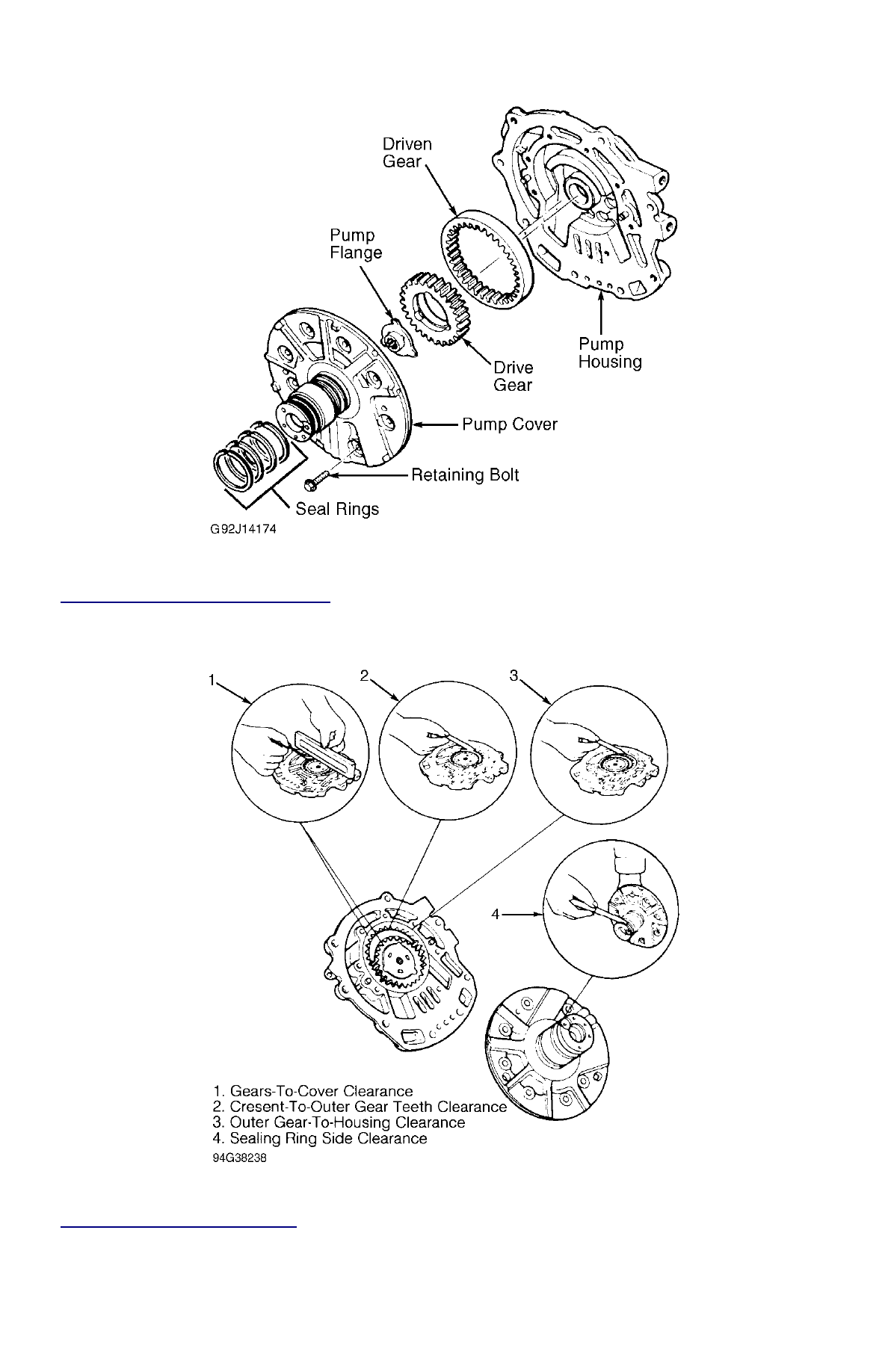
Fig. 19: Exploded View Of Oil Pump Assembly


Courtesy of FORD MOTOR CO. 


Fig. 20: Measuring Oil Pump Clearances


Courtesy of FORD MOTOR CO. 

ONE-WAY CLUTCH 

Disassembly, Inspection & Reassembly 

1. Record direction of rotation one-way clutch locks and turns. Remove snap ring and pull out planetary carrier from one-way clutch inner 

race. See 

Fig. 8

 . Check for worn or damaged parts. Bushing wear on one-way clutch must not exceed 5.120" (130.06 mm).  

2. Check clearance between pinion gears and washers in planetary carrier. If clearance exceeds .031" (.80 mm), replace planetary carrier. 

Reverse disassembly procedure to reassemble. Install one-way clutch in inner race and ensure that it will turn in one direction 
(clockwise) only.  

REAR CLUTCH 

Disassembly 

1. Remove large snap ring. Lift out retaining plate, clutch plates, and dished plate. See 

Fig. 21

 . Using appropriate compressor, compress 

rear clutch spring retainer to remove small snap ring, spring retainer, and clutch return springs.  

2. Place front clutch on oil pump and rear clutch hub on top of front clutch. Apply air pressure to rear clutch oil passage to remove piston. 

See 

Fig. 16

 . Remove and discard piston seal rings.  

Inspection 

Inspect for wear or damage. Ensure return spring free length is 1.031-1.071" (26.20-27.20 mm). 

Reassembly 

1. Install seal rings on piston and install in clutch drum by applying even pressure on perimeter of piston and rotate piston slowly. Install 

return springs and spring retainer. Press spring retainer. Install snap ring. Note direction of dished plate and install. Install driven and 
drive plates, retainer plate and snap ring. See 

Fig. 21

 .  

2. Ensure clearance between snap ring and retainer plate is .031-.039" (.80-1.00 mm). If clearance is not within specification, select correct 

retaining plate. Retaining plates are available in thicknesses .189" (4.80 mm) to .244" (6.20 mm) in .20 mm increments.  

3. Check rear clutch operation by placing forward clutch on oil pump and then rear clutch. Apply compressed air (70 psi maximum) to 

rear clutch oil passage and check operation. See 

Fig. 16

 .  


Fig. 21: Exploded View Of Rear Clutch


Courtesy of FORD MOTOR CO. 

REAR CLUTCH HUB 

Disassembly, Inspection & Reassembly 

Remove snap ring and separate hub from internal gear. Check for worn or damaged snap ring or gear and replace as needed. Reverse 
disassembly procedure to reassemble hub. 

VALVE BODY 

Disassembly 

1. Remove instruction control valve. Remove oil strainer retaining bolts and oil strainer. Remove upper-to-lower valve body retaining bolts. 

Separate valve bodies, separator plate and sub-body. DO NOT lose check balls and springs or orifice valve and spring. See 

Fig. 22

 .  

2. Remove, clean and install each valve individually as needed. See 

Fig. 22

 . Lubricate moving parts with ATF. Ensure all valves move 

(snap) freely. If valve sticks in its bore and cannot be freed, valve body must be replaced. DO NOT attempt to hone valve bores or 
polish valves.  

3. Inspect the valve springs for signs of damage or deformation. Measure valve spring free length and diameter. Refer to the 

VALVE 

NOTE:

Remove and clean one valve at a time to avoid incorrect installation. If any valves, valve springs, or 
valve bodies are damaged, the entire valve body assembly must be replaced.

BODY SPRING DIMENSIONS

 . Reassemble components in reverse order of disassembly.  


Fig. 22: Exploded View Of Valve Body Assembly


Courtesy of FORD MOTOR CO. 

VALVE BODY SPRING DIMENSIONS 

Reassembly 

1. To reassemble, reverse disassembly procedure. Coat all parts with clean transmission fluid. DO NOT force valves into position. Ensure 

orifice check valve, check ball and springs are located correctly.  

2. Place separator plate on lower valve body and hold with clamps. Install upper valve body and bolt into place. Tighten upper valve body 

to lower valve body. See 

Fig. 23

 .  

Application

Free Length In. (mm)

Throttle Back-Up

1.417 (36.00)

Downshift

.862 (21.90)

2-3 Shift (Aspire & Festiva)

1.614 (41.00)

1-2 Shift

1.260 (32.00)

Second Lock

1.319 (33.50)

Pressure Regulator

1.693 (43.00)

Throttle Relief

.441 (11.20)

Orifice Check (Aspire & Festiva)

.610 (15.50)

Steel Ball (Spring)

1.516 (26.80)


Fig. 23: Locating Valve Body Check Balls & Tightening Bolts


Courtesy of GENERAL MOTORS CORP. 

TRANSAXLE CASE 

Inspection 

Inspect case for cracks and stripped threads. Inspect gasket surfaces and mating surfaces for burrs. Check vent for obstructions, and check all 
fluid passages for obstructions and leakage. Inspect case bushing for scores. Check all parking linkage parts for wear or damage. 

TRANSAXLE REASSEMBLY 

OUTPUT SHAFT BEARING PRELOAD 

1. Position output shaft into torque converter housing. Position output shaft outer bearing race in recessed end of Gauge Tool (T87C-

770002DJ). Place gauge tool over output shaft. See 

Fig. 24

 .  

2. Ensure gauge tool is completely threaded together so that no gap is present. Position spacer collars and assemble output bearing and 

idler support to converter housing using supplied bolts and washers of tool set. See 

Fig. 24

 . Tighten bolts to 14-19 ft. lbs. (26 N.m). 

NOTE:

Handle all parts carefully to avoid damaging bearings and mating surfaces. Lubricate all parts with 
clean ATF. Use petroleum jelly on gaskets, thrust washers and needle bearings to retain them in place. 
Soak all friction discs in ATF for at least 15 minutes. Use all new gaskets and seals, and tighten bolts 
evenly.

NOTE:

For identification and position of thrust bearings and washers, see 

Fig. 27

 .


Content   ..  105  106  107  108   ..