Ford Festiva. Instruction - part 102


  Index      Ford     Ford Festiva - service and repair instruction 1991 year


Search            


Content   ..  100  101  102  103   ..


Ford Festiva. Instruction - part 102


Back To Article


WHEEL ALIGNMENT SPECIFICATIONS & PROCEDURES

1991-92 WHEEL ALIGNMENT Ford Motor Co. - Specifications & Procedures 

ADJUSTMENTS 

CASTER 

Caster is permanently set at factory and is not adjustable. Caster should be checked however as a possible cause of suspension complaint. 

CAMBER 

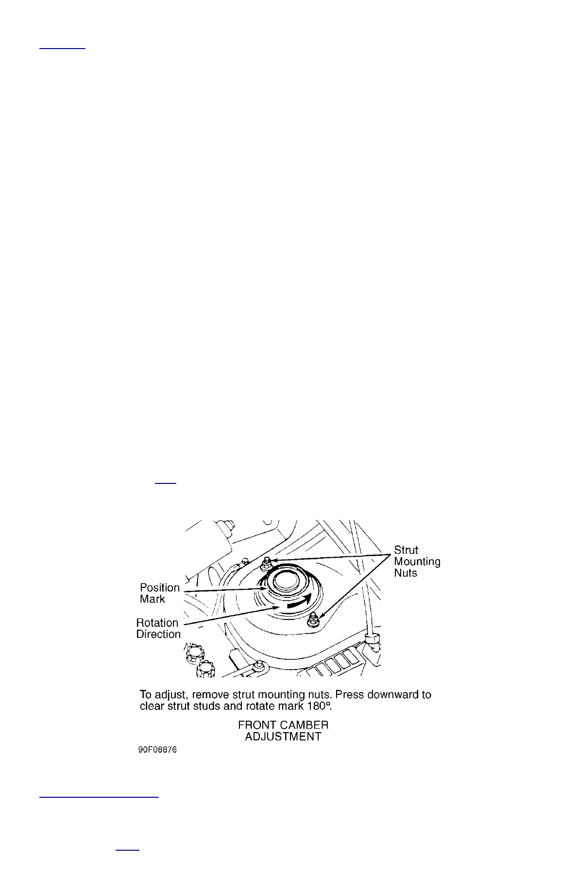
To adjust camber on Festiva, see 

Fig. 1

 . Camber adjustment on Capri is similar. Instead of 2 strut mount studs, Capri has 4 studs. 


Fig. 1: Adjusting Front Camber


Courtesy of FORD MOTOR CO. 

FRONT TOE-IN 

NOTE:

Before adjusting alignment, check riding height. Riding height must be checked with vehicle on level 
floor and tires properly inflated. Bounce vehicle several times and allow suspension to settle.

NOTE:

See 

Fig. 2

 for toe-in adjustment procedures.


Fig. 2: Adjusting Front Toe-In


Courtesy of FORD MOTOR CO. 

REAR TOE-IN 

Festiva 

Capri 

Rear toe should be adjusted before setting front alignment angles. To adjust rear toe, loosen lock nuts and rotate adjustment link on rear 
control arms. 

ALIGNMENT SPECIFICATIONS 

WHEEL ALIGNMENT SPECIFICATIONS (CAPRI) 

WHEEL ALIGNMENT SPECIFICATIONS (FESTIVA) 

TORQUE SPECIFICATIONS 

NOTE:

On Festiva, rear toe is not adjustable.

Application

Preferred

Range

Camber 

(1)


Front

.8

.05 To 1.55

Rear

-.03

-.78 To .72

Caster 

(1)


1.6

.85 To 2.35

Toe-In 

(1)


Front

.3

0 To .6

Rear

.3

0 To .6

Toe-In 

(2)


Front

.15 (4)

0 To .3 (0 To 7.5)

Rear

.15 (4)

0 To .3 (0 To 7.5)

Steering Axis Inclination (SAI) 

(1)


12.36

N/A

(1)

- Measurement in degrees.

(2)

- Measurement in inches (mm).

Application

Preferred

Range

Camber 

(1)


.67

-.25 To 1.58

Caster 

(1)


1.58

.33 To 1.83

Toe-In 

(1)


.28

.04 To .52

Toe-In 

(2)


.14 (3.5)

.02 To .26 (.5 To 6.5)

Steering Axis Inclination (SAI) 

(1)


14.18

N/A

(1)

- Measurement in degrees.

(2)

- Measurement in inches (mm).

TORQUE SPECIFICATIONS (CAPRI) 

TORQUE SPECIFICATIONS (FESTIVA) 

Application

Ft. Lbs. (N.m)

Strut Upper Mounting Nuts

17-21 (23-29)

Tie Rod Jamb Nut

Front

26-30 (35-40)

Rear

41-47 (55-64)

Wheel Lug Nuts

66-87 (89-118)

Application

Ft. Lbs. (N.m)

Strut Upper Mounting Nuts

32-45 (43-61)

Tie Rod Jamb Nut

22-37 (30-50)

Wheel Lug Nuts

66-87 (89-118)

Copyright 2009 Mitchell Repair Information Company, LLC.  All Rights Reserved. 


Article GUID: A00054866 

Back To Article


1988-94 AUTOMATIC TRANSMISSIONS

Ford ATX Overhaul 

APPLICATION 

APPLICATION 

DESCRIPTION 

The transaxle consists of 3 main units: automatic transaxle, torque converter and differential assembly. The automatic transaxle consists of 
front and rear clutches, one-way clutch, low-reverse brake assembly, oil pump and hydraulic controls (valve body and servo piston 
assemblies). The valve body is controlled by the governor valve, vacuum throttle valve diaphragm (modulator) and kickdown solenoid. The 
torque converter on the Aspire model is a mechanically operated (centrifugal type) torque converter clutch. See 

Fig. 1

 . 


Fig. 1: Transaxle Component Identification


Courtesy of FORD MOTOR CO. 

LUBRICATION & ADJUSTMENTS 

See the appropriate TRANSMISSION SERVICING - A/T article in this section. Refer to the following menu: 

ON-VEHICLE SERVICE 

BAND APPLY SERVO R & I 

Removal 

1. Raise and support vehicle. Remove left front wheel. Drain transaxle fluid. Remove valve body. See 

VALVE BODY

 . Remove front 

stabilizer frame brackets. Carefully raise staked portion of left axle nut. Apply brakes and loosen, but DO NOT remove, axle nut. 
Remove left lower control arm ball joint clamp bolt. Pry downward on lower control arm to separate control arm from knuckle.  

2. Insert pry bar between transaxle case and left axle flange. Carefully apply force to pry bar until axle circlip is disengaged. Slide knuckle 

assembly off axle shaft, and remove axle from vehicle. Quickly install appropriate plug in transaxle.  

3. Loosen band adjusting stop and band adjusting stop nut. Remove band strut. Using "C" clamp and socket, compress servo piston into 

transaxle case. See 

Fig. 2

 . Remove snap ring. Remove servo retainer, servo piston and spring.  

Installation 

1. Lubricate servo piston with ATF. Assembly servo retainer, piston, piston large seal and spring. Insert assembly into transaxle. Using "C" 

clamp and socket, compress assembly and install snap ring. See 

Fig. 2

 . Install band strut to intermediate band. Install band adjusting 

stop to band and tighten to 9-10 ft. lbs. (12-15 N.m). Loosen adjusting stop 3 turns. Install and tighten band adjusting stop nut. See 

TORQUE SPECIFICATIONS

 .  

2. Install remaining components in reverse order of disassembly. Fill transaxle with fluid.  

Application

Transmission

1988-89 Mercury Tracer

ATX

1988-93 Ford Festiva

ATX

1994 Ford Aspire

ATX

NOTE:

The ATX transaxle is used in some Mazda models and is referred to as the F3A for those models. The 
ATX transaxle is also used in some General Motors and Isuzu models and may be referred to as the 
KF100, KF400 or RMC. Some of the figures used in this article are courtesy of General Motors Corp. and 
are valid figures for this Ford Motor Co. transaxle.


Content   ..  100  101  102  103   ..