Ford Festiva. Instruction - part 95
Back To Article
STEERING SYSTEM - POWER
1991-92 STEERING Ford Motor Co. - Steering - Power Rack & Pinion
DESCRIPTION & OPERATION
Power steering system consists of a rack and pinion steering gear, valve body, power steering pump, fluid reservoir and interconnecting
hydraulic lines. Pressure and return lines from pump are connected to valve body. A vane-type power steering pump draws fluid from the
steering reservoir. Fluid is compressed by rotor and vanes inside steering pump and sent to steering gear. Pressure is monitored and controlled
by a pressure switch and a control valve located inside of steering pump.
TROUBLE SHOOTING
Refer to TROUBLE SHOOTING - BASIC PROCEDURES article in the GENERAL TROUBLE SHOOTING section.
LUBRICATION
CAPACITY
Information is not available.
FLUID TYPE
Use Dexron-II ATF type fluid.
FLUID LEVEL CHECK
Check fluid level before engine is started, while fluid is still cool. Remove reservoir cap fluid indicator on steering pump. Check fluid level.
Fluid should be between the "L" and "H" marks on the level gauge dipstick. If fluid is needed, fill to the "L" mark on dipstick. Run engine until
warm and turn steering wheel fully in both directions about 10 times. Return steering to straight-ahead position and shut engine off. Ensure
fluid level is between "L" and "H" marks. Add fluid if necessary.
HYDRAULIC FLUID BLEEDING
1. Raise and support front of vehicle. Ensure pump reservoir is filled to specified level. With ignition coil wire disconnected, crank engine
and add fluid to steering pump until fluid level remains constant. While cranking engine, rotate steering from stop to stop. Recheck and
add fluid as necessary.
2. Start engine and allow to idle for several minutes. Turn steering wheel completely lock-to-lock several times. Check fluid level. Add
fluid as necessary. Continue this procedure until there is no bubbling or decrease in fluid level.
ADJUSTMENTS
BELT TENSION
On Festiva, remove air duct and air cleaner. On all models, loosen steering pump mounting pivot bolt and the adjusting bolt lock nut. Using
Belt Tension Gauge (021-0028A), fit gauge to longest available belt span for testing. Adjust belt to specification. See
BELT TENSION
SPECIFICATIONS
. Tighten adjuster lock nut to 32-45 ft. lbs. (43-61 N.m) on Capri or 27-38 ft. lbs. (37-52 N.m) on Festiva.
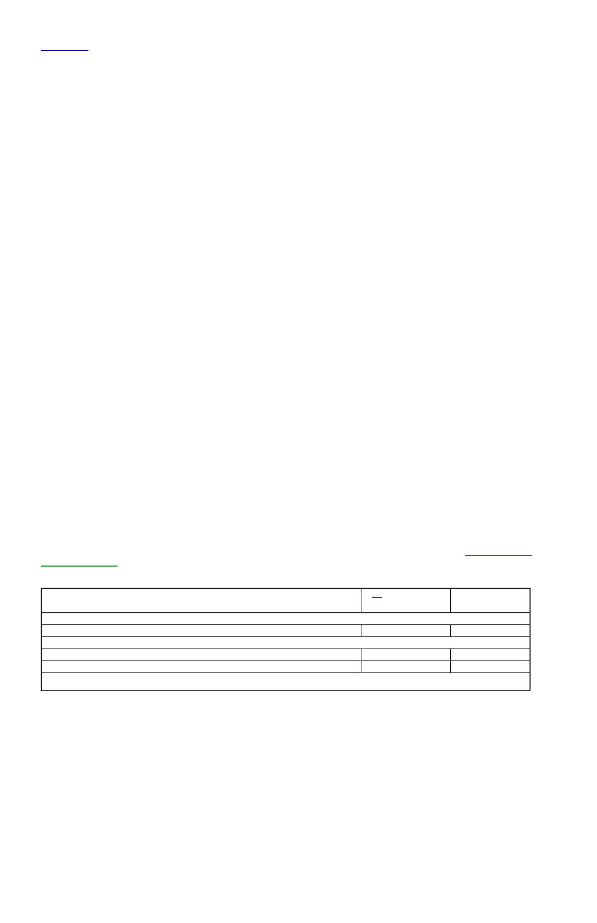
BELT TENSION SPECIFICATIONS
REMOVAL & INSTALLATION
STEERING GEAR
Removal
1. Disconnect negative battery cable. On Capri, mark and loosen intermediate lower U-joint. On Festiva, mark and remove steering gear
intermediate shaft connecting steering gear to column shaft. On all models, disconnect high pressure and return lines and plug them.
Loosen front wheel lug nuts.
2. Raise vehicle. Remove front wheels. Remove tie rod end cotter pins and nuts. Separate tie rod ends from steering knuckles using Tie
Rod Remover (T85M-3395-A). Remove tie rod end splash shields. Remove right fender splash shield. Remove front catalytic converter
nuts and separate converter from inlet pipe.
3. Place reference marks on tie rod end and tie rod for reassembly reference. Loosen tie rod jam nut and remove right tie rod end. Remove
steering gear mounting bolts and washers. Slide steering gear to the left and pull right tie rod through fender opening. Remove steering
gear by sliding it to the right.
Installation
Application
(1)
Deflection: In.
(mm)
Gauge Tension:
Lbs. (kg)
New Belt
Capri & Festiva
.31-.35 (8-9)
110-132 (50-60)
Used Belt
Capri
.31-.35 (8-9)
110-132 (50-60)
Festiva
.35-.39 (9-10)
95-110 (43-50)
(1)
Apply approximately 22 lbs. (9.9 kg) of pressure.