Ford Festiva. Instruction - part 94


  Index      Ford     Ford Festiva - service and repair instruction 1991 year


Search            


Content   ..  92  93  94  95   ..


Ford Festiva. Instruction - part 94


Back To Article


SERVICE INDICATOR & WARNING LIGHTS

1988-92 MAINTENANCE Ford Motor Co. Service Indicator & Warning Lights 

SERVICE INDICATOR & WARNING LIGHTS 


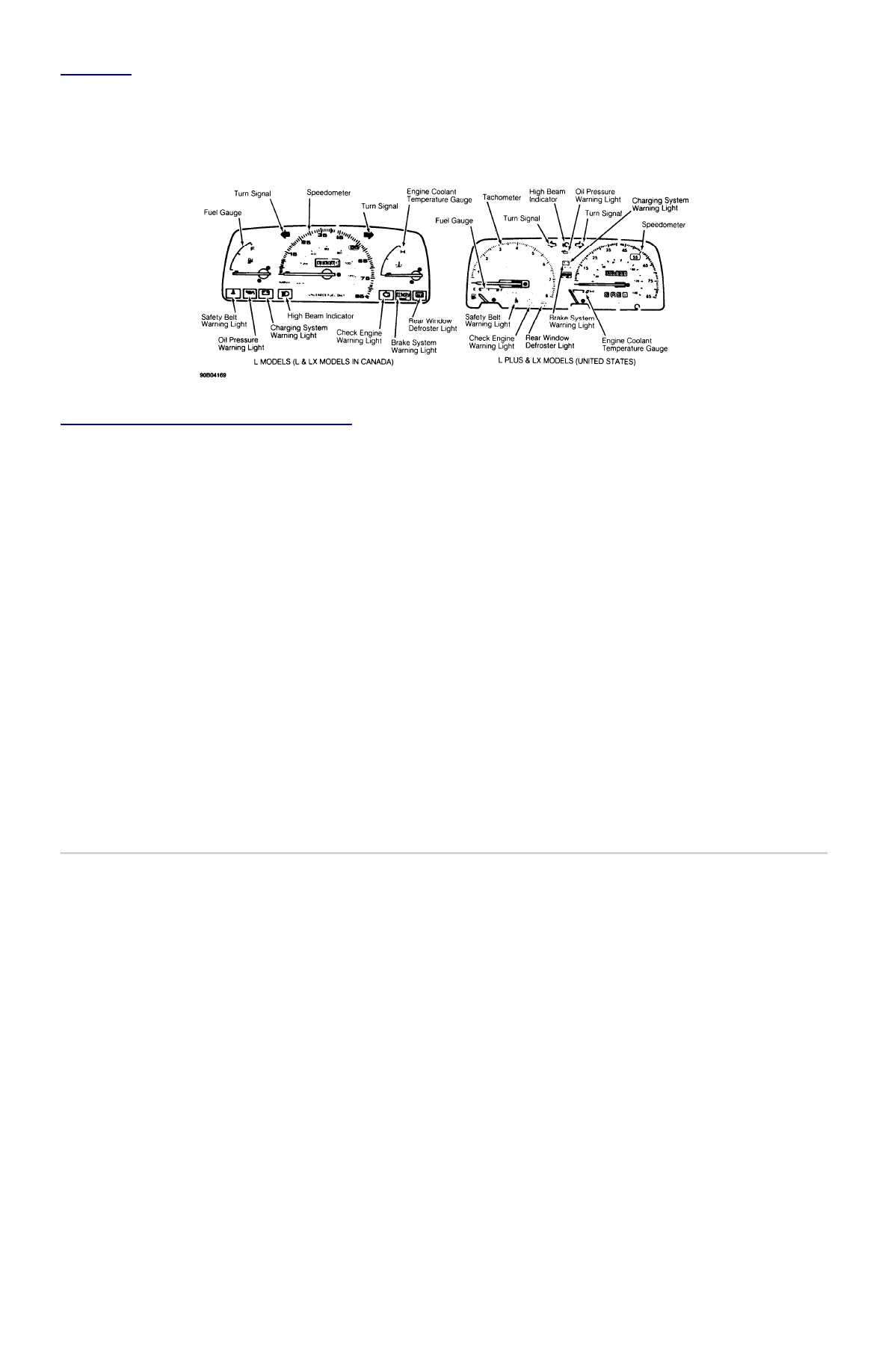
Fig. 1: Identifying Dash Gauges & Warning Lights


Courtesy of FORD MOTOR CO. 

CHECK ENGINE WARNING LIGHT 

If functioning properly, the Check Engine warning light comes on when ignition switch is in the ON position and goes out after engine is 
started. If light fails to glow with ignition on or remains on when engine is running, a malfunction exists in the electronic engine control 
system. System needs to be checked and serviced. 

CHARGING SYSTEM WARNING LIGHT 

Light comes on when ignition switch is in the ON or START position and goes out after engine is started and alternator is charged. Light may 
also glow when there is a heavy electrical load on the system. If light remains on after reducing electrical load, check electrical system. 

OIL PRESSURE WARNING LIGHT 

Light should come on briefly and go out after engine is started. If light remains on with engine running, oil pressure is low. Check oil level. 

ENGINE COOLANT TEMPERATURE GAUGE 

Gauge should register within the NORMAL band under regular operating conditions. If gauge rises into the HOT range, stop engine, allow it to 
cool, and then check coolant level. 

BRAKE WARNING LIGHT 

The Brake light indicates one of 2 conditions: parking brake is engaged, or malfunction exists in the dual braking system. If functioning 
properly, light should come on briefly with ignition switch in the ON position and then go out after engine is started and parking brake is 
released. If light remains on, a malfunction is indicated. Service brake system. 

Copyright 2009 Mitchell Repair Information Company, LLC.  All Rights Reserved. 


Article GUID: A00062872 

Back To Article


STEERING SYSTEM - MANUAL 

1991 STEERING Ford Motor Co. - Steering - Instruction Rack & Pinion 

DESCRIPTION 

Rack and pinion type steering is mounted on rubber insulators to the chassis bulkhead. Adjustment is provided for pinion gear preload. Pinion 
shaft is coupled to steering shaft. Tie rods connect end of rack to steering knuckles. 


Fig. 1: Exploded View of Instruction Steering Gear Assembly


Courtesy of FORD MOTOR CO. 

TROUBLE SHOOTING 

Refer to TROUBLE SHOOTING - BASIC PROCEDURES article in the GENERAL TROUBLE SHOOTING section. 

ADJUSTMENTS 

Necessary adjustments are made during reassembly procedure. See 

OVERHAUL

 . 

REMOVAL & INSTALLATION 

STEERING GEAR 

Removal 

1. Raise and support vehicle. Remove front wheels. Remove vehicle battery. Remove cotter pins and castle nuts from tie rod ends. Using 

tie rod puller, separate tie rod ends from steering knuckles. Remove the catalytic converter.  

2. Remove plastic splash shield from right side lower inner fender panel. Mark the lower steering column "U" joint for reassembly 

reference and disconnect steering column and intermediate shaft. Remove steering gear bracket bolts. Lower steering gear until steering 
shaft is clear of column boot.  

3. Slide steering gear to the right, through the inner fender tie rod opening until the left tie rod clears the left fender opening. Lower left 

side of steering gear until it can be removed from the left side. Ensure rack boots are not pinched or damaged during removal.  

Installation 

To install, reverse removal procedure. Check and adjust toe-in. See WHEEL ALIGNMENT SPECIFICATIONS & PROCEDURES article in 

the WHEEL ALIGNMENT section. 

OVERHAUL 

STEERING GEAR 

Disassembly 

1. With steering gear removed from vehicle, place steering gear in a soft-jawed vise. Mark threaded portion of tie rod for reassembly. 

Remove tie rod ends. Remove tie rod boots. Remove lock pins from both ends of rack. See 

Fig. 1

 .  

2. Remove tie rod ball socket from end of rack. Remove both tie rods. Remove lock nut from yoke plug. Remove yoke plug, spring and 

yoke support. Use a small screwdriver to remove pinion oil seal from pinion shaft. Remove pinion bearing snap ring.  

3. Remove pinion and bearing assembly. If necessary use Valve Body Puller (T78P-3504-B) to remove pinion and bearing assembly. 

Remove rack from pinion side of housing. If lower pinion bearing needs replacing, use Blind Hole Bearing Puller (D80L-100-L) and 
Slide Hammer (T50T-100-A) to remove. 

4. Press bushing lock tabs into the 3 slots located at end of rack housing. Use Blind Hole Bearing Puller (D80L-100-L), to remove rack 

support bushing from right end of rack housing.  

Inspection 

1. Check rubber boots, ball bearings and tooth surface of rack for wear or damage. Using a dial indicator and "V" blocks, check rack for 

straightness. Maximum allowable runout is 0.012" (0.3 mm). If rack support bushings are worn, use a screwdriver to release the tab lock 
on the side opposite the pinion. Use blind hole Bearing Puller (D80L-100R) with slide hammer to remove bushing.  

2. Check tie rod ball joints for smooth operation. Replace parts as necessary. Check sliding surface of rack support and gear housing for 

cracks or damage. Check rack bushing for excessive wear. Replace entire gear housing assembly if any of these parts are worn or 
damaged.  

Reassembly 

1. Apply lithium grease to ball bearing, roller bearing, inside of gear housing, lip of oil seal, sliding surface and back of rack support, 

sliding surface of rack bushing, rack pinion teeth and ball joints. Install rack support bushing into right end of rack housing. Ensure lock 
tabs engage with slots in housing.  

2. If previously removed, install a new lower pinion bearing using a bushing installer or a piece of wooden dowel stock. Carefully insert 

non-toothed side of rack into left end of rack housing, with rack teeth facing pinion bore. Position rack in housing so rack protrudes 
2.4" (62 mm) from the left side of housing. Install pinion and upper bearing assembly so that when bearing is seated, notch (for "U" joint 
clamp bolt) in pinion splines forms a 35-55 degree angle with the centerline of the housing. See 

Fig. 2

 . 


Fig. 2: Removing & Installing Rack Components


Courtesy of FORD MOTOR CO. 

3. Install snap ring and spacer, with beveled side of snap ring facing upward (toward oil seal). Install oil seal spacer with tab side down, 

locating tab in snap ring gap. Protect pinion shaft splines with tape. Coat tape with a thin coat of grease and install new seal. Using a soft 
hammer, tap lightly on seal until it is flush with end surface of housing. Remove protective tape.  

4. Mount rack in a soft-jawed vise and install new lock tabs and tie rods. Tighten tie rod with a "crows foot" wrench to 44-58 ft. lbs. (59-

78 N.m). Use a center punch to stake lock tabs washer in 2 places. Slide tie rod boot over tie rod and position on rack. Secure with 
mechanic's tie wire. Install other boot and other boot clamps.  

5. Center rack so that tie rods are equally extended. Grease rack support yoke. Install rack support yoke, spacer and spring in housing. 

Apply sealer to adjusting cover (yoke plug) threads and install in housing. Install adjusting bolt and lock nut.  

6. Tighten adjusting cover to 80-97 INCH lbs. (9-11 N.m). Slowly cycle rack back and forth 5 times through 90 percent of its full stroke. 

Center rack so tie rods are equally extended. Loosen adjusting cover and retighten to 22-30 INCH lbs. (2.5-3.4 N.m). Using a spring pull 
scale, measure force needed to turn pinion 180 degrees from center rack position.  

7. Adjust pinion to position where most force was needed to turn it. Tighten adjusting cover to 48 INCH lbs. (5.4 N.m), then back off 5-10 

degrees. Hold adjusting bolt with a wrench and tighten the lock nut with a "crows foot" to 29-36 ft. lbs. (39-49 N.m). 8) To complete 
reassembly, reverse disassembly procedure. Install tie rod ends and jam nuts. Ensure index marks align. See 

Fig. 1

 .  

CAUTION:

If rack is taken out of wrong side, damage may result to rack bushing.

NOTE:

If fit between housing and bearing is too tight, strike outer ring of bearing lightly while checking 
mesh of rack and pinion.

WHEEL ALIGNMENT 

After performing appropriate service procedures, refer to WHEEL ALIGNMENT SPECIFICATIONS & PROCEDURES article in the WHEEL 
ALIGNMENT section. 

TORQUE SPECIFICATIONS 

TORQUE SPECIFICATIONS 

Application

Ft. Lbs. (N.m)

Pinion Adjusting Screw Lock Nut

29-36 (39-49)

Mounting Bracket Bolt

23-34 (31-46)

Tie Rod End Castle Nut

26-30 (35-40)

Tie Rod-to-Rack Ball Joint

43-58 (58-79)

Copyright 2009 Mitchell Repair Information Company, LLC.  All Rights Reserved. 


Article GUID: A00054859 


Content   ..  92  93  94  95   ..