Ford Festiva. Instruction - part 29
2. Remove main bearing cap bolts. Remove cap and lower bearing insert. Use bearing remover or fabricated cotter key to remove upper
bearing insert. Insert bearing remover in journal lubrication hole. Rotate crankshaft in normal direction of operation only. Repeat
procedure for remaining main bearings.
3. Check bearings for abnormal wear. Check crankshaft for grooves, scratches and pitting. Using Plastigage method, check clearance of
main bearing-to-crankshaft. Always keep at least 2 bearings and caps tight during clearance check. See, at end of article,
CRANKSHAFT MAIN & CONNECTING ROD BEARINGS
table under ENGINE SPECIFICATIONS.
4. Lubricate and install new bearings in cap and block. Match bearing tangs with notch in cap and block. Position cap in its proper
location and position. Install cap bolts and tighten to specification. See
TORQUE SPECIFICATIONS
table at end of article. Repeat
procedure for remaining main bearings.
CRANKSHAFT END PLAY
Check crankshaft end play with dial indicator. End play should be .0031-.0111" (.08-.282 mm). Service limit is .012" (.30 mm). If end play is
not within specification, replace thrust bearings as necessary.
CYLINDER BLOCK
1. Using straightedge and feeler gauge, check entire cylinder head surface of cylinder block. Ensure warpage does not exceed .006" (.15
mm). If warpage exceeds specification, cylinder block surface can be machined a maximum of .008" (.20 mm).
2. Replace cylinder block if it needs to be machined more than .008" (.20 mm). Check cylinder bore for wear, out-of-round, taper and
piston fit. See
CYLINDER BORE SPECIFICATIONS
table. Oversize pistons are available in .010" and .020" (.25 mm and .50 mm).
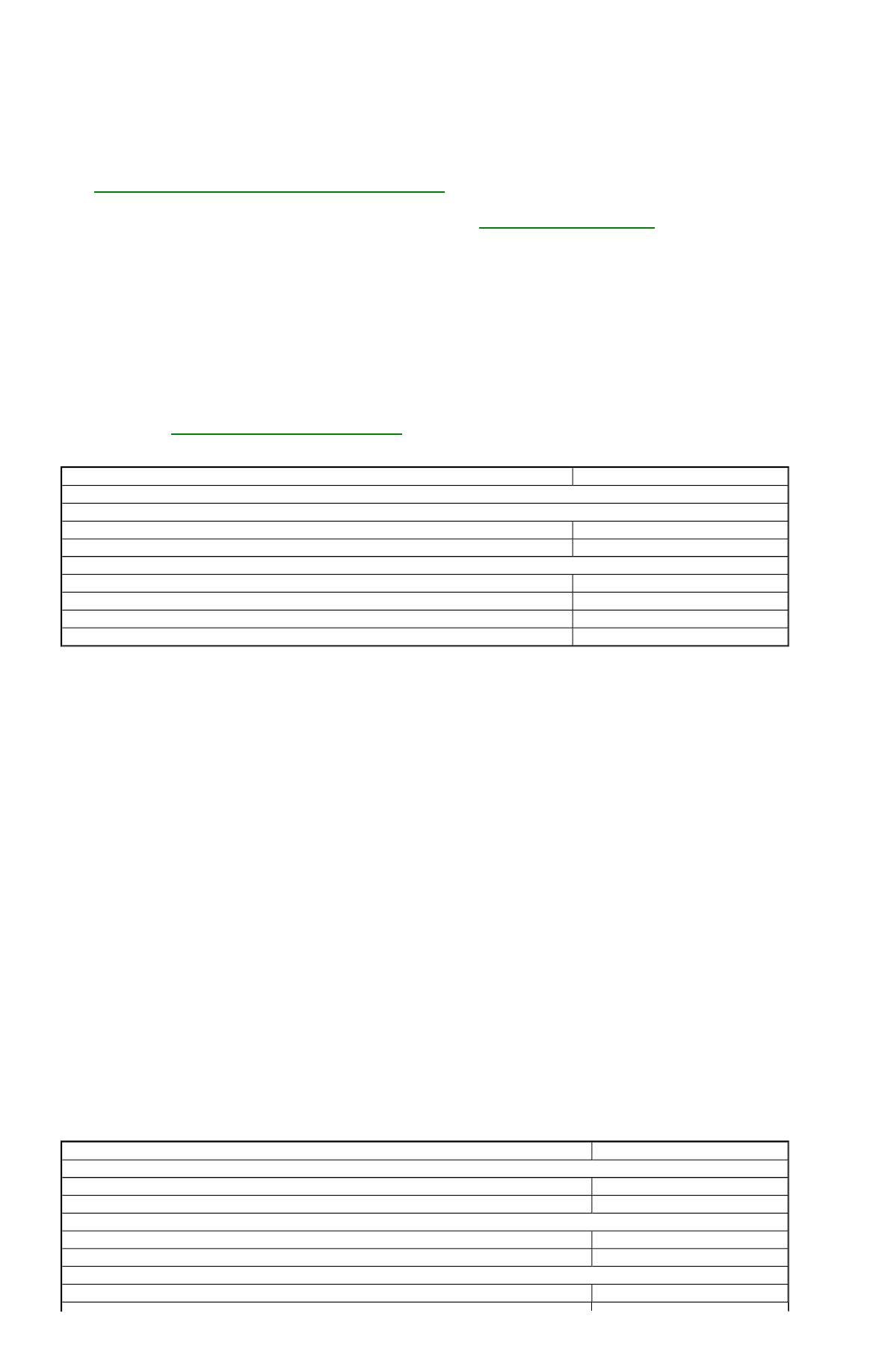
CYLINDER BORE SPECIFICATIONS
LUBRICATION
ENGINE OILING SYSTEM
Oiling system is force-feed type and uses a full-flow oil filter. Oil is retrieved from oil pan by oil pump pick-up tube and distributed to oil
filter. Oil is then filtered and routed throughout engine.
Crankcase Capacity
1.3 L crankcase capacity is 3.2 qts. (3.0 L) without filter change and 3.6 qts. (3.4 L) with filter change. For 1.6 L vehicles, capacity is 3.2 qts
(3.2 L) without filter and 3.72 qts. (3.5 L) with filter.
Normal Oil Pressure (Hot)
Normal oil pressure is 50-64 psi (3.5-4.5 kg/cm
2
) at 3000 RPM.
Pressure Regulator Valve
Pressure regulator valve is located in oil pump body and is nonadjustable.
OIL PUMP
Removal
Remove oil pan, pick-up tube and screen, timing belt and crankshaft sprocket. Remove front engine cover bolts and remove front cover.
Remove bolts retaining pump cover to back side of front cover housing.
2) Remove pump cover and inner and outer gears. Pry out front seal from front cover. Remove cotter pin. Remove pressure regulator retainer,
spring and valve.
OIL PUMP SPECIFICATIONS
or replacement.
Application
In. (mm)
Cylinder Diameter
Standard Bore
1.3L
2.7953-2.7960 (71.000-71.019)
1.6L
3.0709-3.0716 (78.000-78.019)
Maximum Bore
1.3L
2.8020 (71.17)
1.6L
3.0905-3.0913 (78.500-78.519)
Maximum Out-Of-Round & Taper
.0007 (.019)
Piston-To-Bore Clearance
.006 (.15)
Application
In. (mm)
Inner Gear-To-Outer Gear
1.3L
.008 (.20)
1.6L
.0008-.0063 (.02-.16)
Outer Gear-To-Housing
1.3L
.009 (.22)
1.6L
.0035-.0071 (.09-.18)
End Play
1.3L
.006 (.14)