Ford Festiva. Instruction - part 28


  Index      Ford     Ford Festiva - service and repair instruction 1991 year


Search            


Content   ..  26  27  28  29   ..


Ford Festiva. Instruction - part 28


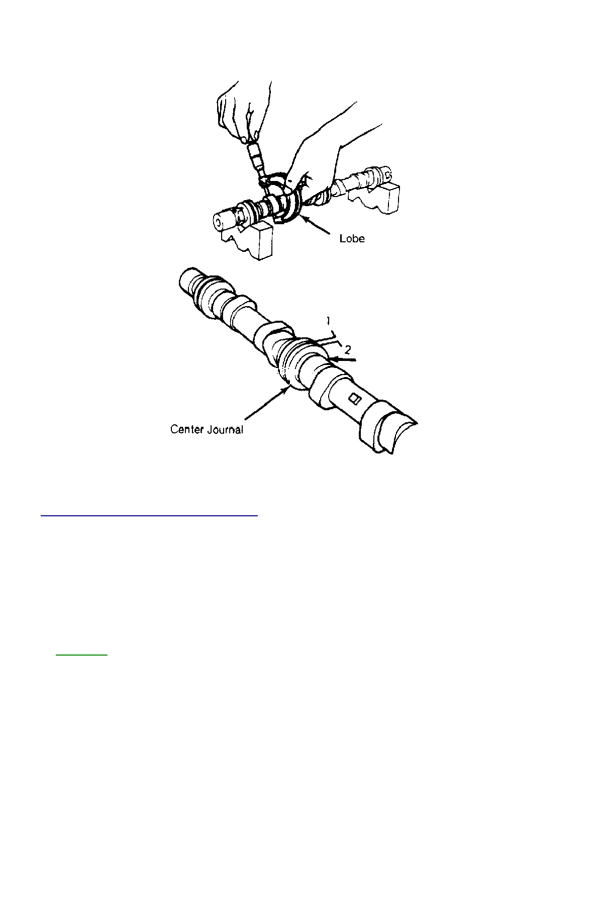
Fig. 7: Measuring Camshaft (1.3L Shown; 1.6L Similar)


Courtesy of FORD MOTOR CO. 

CAMSHAFT END PLAY 

1. Measure camshaft end play with thrust plate in position. Install dial indicator to front of head, with pointer on camshaft center. Pry 

camshaft fully rear, and zero dial indicator.  

2. Pry camshaft fully forward and note dial indicator reading. Standard end play is .002-.007" (.05-.18 mm) with a limit of .008" (.20 mm). 

If end play exceeds specification on 1.3L engines, replace thrust plate and recheck end play. If end play is exceeded on 1.6L engines, 
replace camshaft and/or cylinder head.  

CAMSHAFT OIL SEAL 

See 

CAMSHAFT

 . 

REAR MAIN BEARING OIL SEAL 

Removal (1.3L) 

Remove transaxle. See TRANSMISSION REMOVAL & INSTALLATION article in TRANSMISSION SERVICING. Remove flywheel or 
flexplate. Remove rear engine plate (if equipped). Remove rear main bearing oil seal retainer and press out rear main bearing oil seal. 

Installation (1.3L) 

Clean seal surface in retainer. Lubricate oil seal inside and outside. Install seal retainer on engine. Install seal in retainer with hollow side of 
seal facing engine. Using Rear Main Seal Installer (T87C-6701-A), install rear main bearing oil seal. To complete installation, reverse removal 
procedure. 

Removal (1.6L) 

Remove transaxle. See TRANSMISSION REMOVAL & INSTALLATION article in TRANSMISSION SERVICING. Remove clutch cover and 
disc (if equipped). Remove flywheel or flexplate. Remove rear seal using Seal Remover (T78P-3504-N). 

Installation (1.6L) 

Lubricate oil seal lip with engine oil. Using Rear Main Seal Installer (T87C-6701-A) and Screw Set (T90P-6701-AH), install rear main 

bearing oil seal. To complete installation, reverse removal procedure.

WATER PUMP 

Removal & Installation (1.3L) 

Remove timing belt. Drain cooling system. Remove lower radiator hose and heater return hose from water pump. Remove water pump 
retaining bolts and water pump. Clean gasket mounting surface and replace gasket. To install, reverse removal procedure. 

Removal (1.6L) 

1. Remove timing belt. See 

TIMING BELT

 . Drain cooling system. Remove timing belt tensioner and idler pulleys. Remove oil dipstick 

bracket retaining bolt.  

2. Remove power steering pump from retaining bracket, leaving hoses attached. Remove power steering bracket and position power 

steering pump to one side. Remove water pump outlet. Remove water pump retaining bolts and water pump.  

Installation (1.6L) 

1. Clean all gasket surfaces. Transfer rubber belt cover seal to new water pump (if required). Position water pump with new gasket and 

install retaining bolts. Install pump outlet with new gasket and "O" ring. See 

TORQUE SPECIFICATIONS

 table at end of article.  

2. Install oil dipstick retaining bolt. Install timing belt tensioner and idler pulleys. Install power steering pump bracket. Install power 

steering pump. Tighten all bolts and nuts to specification. See 

TORQUE SPECIFICATIONS

 table at end of article.  

3. Install timing belt. Fill cooling system. Start engine and check for leaks and proper system function.  

OIL PAN 

Removal (1.3L) 

Disconnect battery ground cable. Raise vehicle and drain engine oil. Remove flywheel housing dust cover. Remove oil pan retaining bolts, 
nuts and stiffeners. Rotate crankshaft while removing oil pan. Remove baffle plate from oil pan. Clean gasket mating surfaces thoroughly. 

Installation (1.3L) 

Ensure gasket surfaces are clean. Apply oil resistant sealer to front and rear engine covers and across joint line of cylinder block. 

Removal (1.6L) 

1. Raise vehicle and drain engine oil. Remove frame brace retaining bolt. Loosen RH "A" arm front bolt, and pivot brace downward. 

Disconnect front exhaust pipe from exhaust manifold (or turbocharger). Remove exhaust pipe bracket retaining bolts. Loosen rubber 
exhaust hangers at catalytic converter.  

2. Allow exhaust to hang supported by mechanic's wire. Disconnect turbocharger oil return hose (if equipped). Remove oil pan retaining 

bolts. Carefully pry oil pan loose from cylinder block.  

Installation (1.6L) 

1. Clean pan and block gasket surfaces. Apply Gasket Sealant (E3AZ-19562-A) to new front and rear pan seals. Install seals to cylinder 

block. Apply Gasket Sealant (E3AZ-19562-A) to oil pan gasket surface. See 

Fig. 8

 . Install oil pan and tighten pan retaining bolts to 

specification. See 

TORQUE SPECIFICATIONS

 table at end of article.  

2. Connect turbocharger oil return hose (if equipped). Install rubber exhaust hanger to brackets. Install new gasket and connect front 

exhaust pipe to exhaust manifold (or turbocharger). Install front exhaust pipe bracket. Tighten nuts and bolts to specification.  

3. Pivot frame brace into position. Tighten retaining bolt to crossmember and RH "A" arm front retaining bolt to specification. Lower 

vehicle, fill with oil and start engine. Check for oil leaks and system operation.  

NOTE:

Raise engine slightly with floor jack, if required, to gain clearance for water pump removal.

CAUTION:

DO NOT force a pry tool between cylinder block and oil pan.


Fig. 8: Identifying Oil Pan Sealing Points


Courtesy of FORD MOTOR CO. 

OVERHAUL 

VALVE SPRINGS 

Measure valve springs squareness and free length. Replace spring if either measurement is out of specification. See, at end of article, 

VALVES 

& VALVE SPRINGS

 table in ENGINE SPECIFICATIONS. 

VALVE STEM INSTALLED HEIGHT 

Measure protruding length of each valve stem. See VALVE STEM INSTALLED HEIGHT table. If length is at service limit, use valve spring 
shims to bring measurement within range of acceptable limit. If length is greater than service limit, replace valve seat or cylinder head. 

VALVE STEM INSTALLED HEIGHT 

VALVE GUIDES 

Remove cylinder head, camshaft(s) and valves. Check valve stem-to-guide oil clearance. If clearance exceeds specification, replace valve 
guides and/or valves. See 

CYLINDER HEAD

 table under ENGINE SPECIFICATIONS at end of this article. 

ROCKER ARM SHAFT ASSEMBLY (1.3L) 

Remove valve cover. Keep components in order of removal to ensure reassembly to original position. Remove rocker arm shaft retaining bolts 
and rocker arm shaft assembly. To install, reverse removal procedure. 

VALVE LASH ADJUSTERS (1.3L) 

Warm engine to normal operating temperature. Remove valve cover. Inspect hydraulic lash adjuster operation by pushing each rocker arm 
down by hand. If rocker arm moves downward, replace hydraulic lash adjuster. Adjustment on valve lash adjusters is NOT possible or 
necessary. 

CAM SHAFT(S) (1.6L) 

Remove cam cover. Remove camshaft(s). Keep components in order of removal to ensure reassembly to original position. To install, reverse 
removal procedure. 

VALVE LASH ADJUSTERS (1.6L) 

Inspect friction surfaces for wear and damage. Hold bucket body (each adjuster) and press between thumb and forefinger. If plunger moves, 

Application

In. (mm)

1.3L

New

1.520-1.539 (38.6-39.1)

Acceptable Limit

1.539-1.579 (39.2-40.1)

Service Limit

1.579 (40.1)

1.6L

New

1.713-1.732

Acceptable Limit

1.7732-1.772 (44-45)

Service Limit

1.772 (45)

NOTE:

For additional valve specifications, see, at end of this article, 

VALVES & VALVE SPRINGS

 table under 

ENGINE SPECIFICATIONS.

replace hydraulic lash adjuster. Adjustment on valve lash adjusters is NOT possible or necessary.

PISTON & ROD ASSEMBLY 

1. Remove cylinder head assembly. Remove oil pan. Mark connecting rod caps for reassembly reference. Remove rod nuts. Remove lower 

rod cap and bearing. Tap piston out top of cylinder block. DO NOT scratch crank journal or cylinder walls during removal.  

2. Repeat procedure for remaining pistons. Keep removed parts in order to ensure installation to original position. Position piston assembly 

in correct cylinder bore. Align piston mark "F" (1.3L), or notch (1.6L) located at piston pin bore area, and connecting rod oil groove 
toward engine front. To complete installation, reverse removal procedure. Tighten all bolts and nuts to specification. See 

TORQUE 

SPECIFICATIONS

 table at end of article.  

FITTING PISTONS 

1. With piston assembly removed, remove piston rings and clean piston. Measure piston outer diameter in thrust direction, below oil ring 

groove. Diameter is 2.793-2.794" (70.954-70.974 mm) for 1.3L engines and 3.0690-3.0698 (77.954-77.974) for 1.6L engines.  

2. Place piston upside down in cylinder from which it was removed. Using a feeler gauge, measure clearance between piston and cylinder 

bore. If clearance is not within specification, bore cylinder and replace piston as necessary. See 

CYLINDER BLOCK

table in ENGINE 

SPECIFICATIONS at end of article.  

PISTON RINGS 

Install rings on piston. Ensure marked side of rings are in proper position. Set ends of rings to proper position. See 

Fig. 9

 . 


Fig. 9: Positioning Piston Rings


Courtesy of FORD MOTOR CO. 

PISTON PIN REPLACEMENT 

1. With piston removed and cleaned, mark piston-to-rod to ensure proper reassembly. Using Piston Pin Remover/Installer Set (D81L-6135-

A for 1.3L or D90P-6135-AH for 1.6L), place piston and rod assembly in press.  

2. Apply pressure and press piston pin from piston assembly. Keep all removed components together for reassembly. Remove piston and 

rod from press and inspect.  

3. Using a micrometer, measure piston pin O.D. in several areas. Measure piston pin I.D. Measure I.D. of piston pin bore and rod pin bore. 

Replace components if not within specifications. See, at end of article, 

PISTONS PINS & RINGS

 table in ENGINE 

SPECIFICATIONS  

4. If measurements of rod, piston and pin are within specification, reassemble using piston pin assembly set. Ensure piston-to-rod position 

is proper, with connecting rod oil groove on side of piston marked "F" or by a notch. Lubricate pin with engine oil before reassembly. 
With piston assembly reassembled, rod should fall by its own weight with piston held horizontally. Repeat procedure for remaining 
pistons.  

Rod Bearings Check rod bearing for abnormal wear. Check crankshaft journal. Check rod bearing-to-crankshaft clearance with Plastigage. 
Machine or replace as necessary. See, at end of article, 

CRANKSHAFT MAIN & CONNECTING ROD BEARINGS

table under ENGINE 

SPECIFICATIONS. 

CRANKSHAFT & MAIN BEARINGS 

1. Drain oil and remove oil pan. Ensure main bearing caps are marked for installation to original location and position. 

NOTE:

Installation press pressure for piston pins is 1100-3300 lbs. (500-1500 Kg)

NOTE:

If replacing bearing inserts with engine in vehicle, remove one bearing at a time for measurement 


Content   ..  26  27  28  29   ..