Ford Fiesta (1989-1995). Instruction - part 35
7
Fuel pump/fuel pressure -
checking
3
Note: Refer to the warning note in Section 1
before proceeding.
Fuel pump operation check
1 Switch on the ignition, and listen for the fuel
pump (the sound of an electric motor running,
audible from beneath the rear seats).
Assuming there is sufficient fuel in the tank,
the pump should start and run for
approximately one or two seconds, then stop,
each time the ignition is switched on. Note: If
the pump runs continuously all the time the
ignition is switched on, the electronic control
system is running in the backup (or “limp-
home”) mode referred to by Ford as “Limited
Operation Strategy” (LOS). This almost
certainly indicates a fault in the EEC IV module
itself, and the vehicle should therefore be
taken to a Ford dealer for a full test of the
complete system, using the correct diagnostic
equipment; do not waste time or risk
damaging the components by trying to test
the system without such facilities.
2 Listen for fuel return noises from the fuel
pressure regulator. It should be possible to
feel the fuel pulsing in the regulator and in the
feed hose from the fuel filter.
3 If the pump does not run at all, check the
fuse, relay and wiring (see Chapter 12). Check
also that the fuel cut-off switch has not been
activated and if so, reset it.
Fuel pressure check
4 A fuel pressure gauge will be required for
this check and should be connected in the
fuel line between the fuel filter and the fuel rail,
in accordance with the gauge maker’s
instructions. On Zetec engines, a pressure
gauge equipped with an adapter to suit the
Schrader-type valve on the fuel rail pressure
test/release fitting (identifiable by its blue
plastic cap, and located on the union of the
fuel feed line and the fuel rail) will be required.
If the Ford special tool 29-033 is available, the
tool can be attached to the valve, and a
conventional-type pressure gauge attached to
the tool.
5 If using the service tool, ensure that its tap
is turned fully anti-clockwise, then attach it to
the valve. Connect the pressure gauge to the
service tool. If using a fuel pressure gauge
with its own adapter, connect it in accordance
with its maker’s instructions.
6 Start the engine and allow it to idle. Note
the gauge reading as soon as the pressure
stabilises, and compare it with the regulated
fuel pressure figures listed in the
Specifications.
a) If the pressure is high, check for a
restricted fuel return line. If the line is
clear, renew the fuel pressure regulator.
b) If the pressure is low, pinch the fuel return
line. If the pressure now goes up, renew
the fuel pressure regulator. If the pressure
does not increase, check the fuel feed
line, the fuel pump and the fuel filter.
7 Detach the vacuum hose from the fuel
pressure regulator; the pressure shown on the
gauge should increase. Note the increase in
pressure, and compare it with that listed in the
Specifications. If the pressure increase is not
as specified, check the vacuum hose and
pressure regulator.
8 Reconnect the regulator vacuum hose, and
switch off the engine. Verify that the hold
pressure stays at the specified level for five
minutes after the engine is turned off.
9 Carefully disconnect the fuel pressure
gauge, depressurising the system first as
described in Section 2. Be sure to cover the
fitting with a rag before slackening it. Mop up
any spilt petrol.
10 Run the engine, and check that there are
no fuel leaks.
8
Fuel tank - removal,
inspection and refitting
3
Proceed as described in Part A, Section 8,
but before disconnecting the battery, relieve
the residual pressure in the fuel system (see
Section 2), and equalise tank pressure by
removing the fuel filler cap.
9
Fuel pump/fuel gauge
sender unit - removal and
refitting
3
Refer to Part B, Section 9.
10 Fuel tank ventilation tube -
removal and refitting
3
Refer to Part A, Section 10, but note that
the ventilation tube connects to the combined
roll-over/anti-trickle-fill valve assembly but,
instead of venting to atmosphere, a further
tube runs the length of the vehicle to the
evaporative emission control system carbon
canister in the front right-hand corner of the
engine compartment.
Further information on the evaporative
emission control system is contained in Part E
of this Chapter.
11 Fuel tank filler pipe -
removal and refitting
3
Refer to Part A, Section 11.
12 Fuel cut-off switch -
removal and refitting
1
Refer to Part B, Section 12.
13 Fuel injection system -
checking
3
Refer to Part B, Section 13
14 Fuel injection system
components - removal and
refitting
3
Note: Refer to the warning note in Section 1
before proceeding.
Throttle housing
1 Disconnect the battery negative (earth) lead
(refer to Chapter 5A, Section 1).
2 Remove the air inlet components as
described in Section 4.
3 Disconnect the accelerator cable from the
throttle linkage (see Section 5).
4 Disconnect the throttle position sensor
multi-plug.
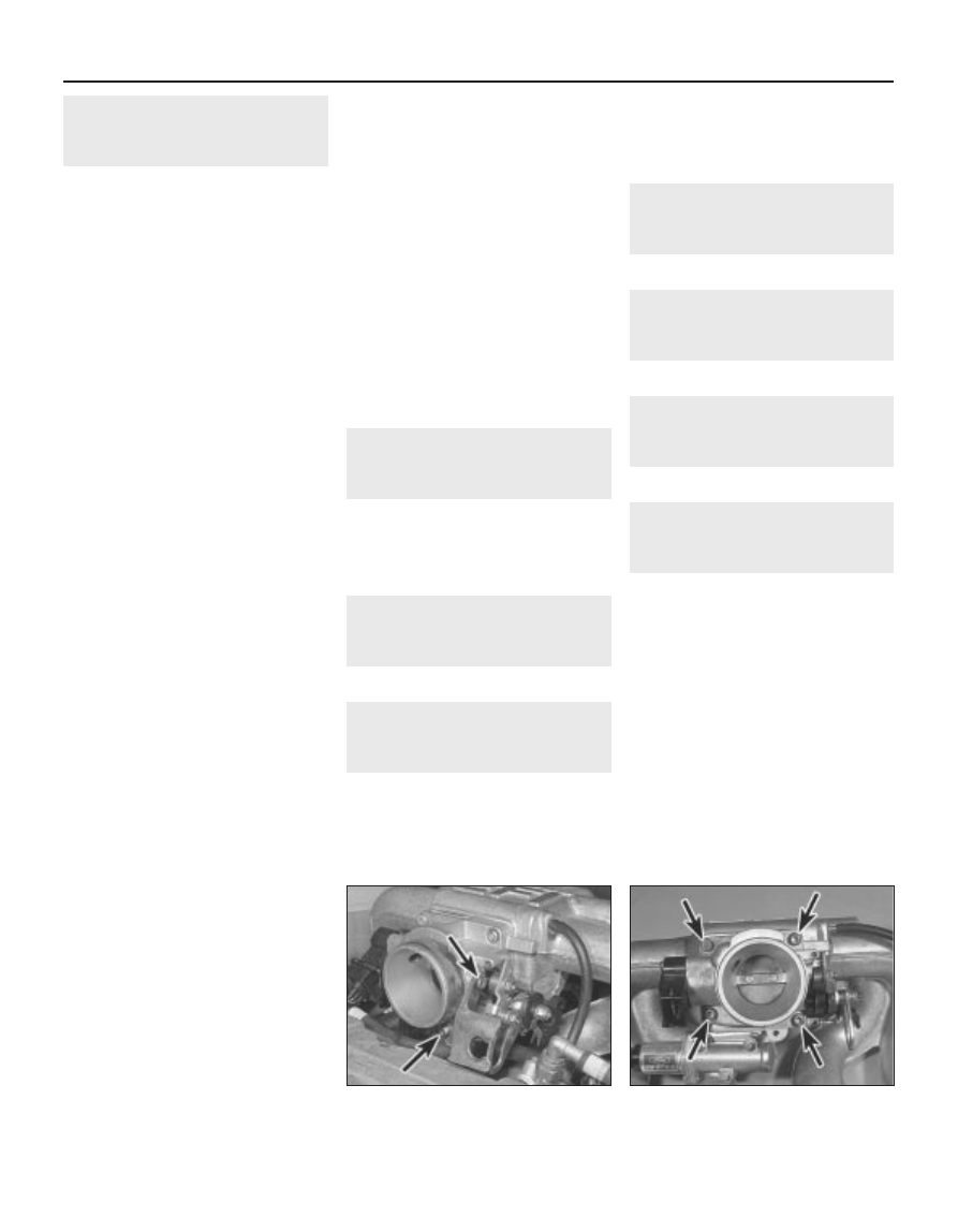
5 Unscrew the retaining bolts, and detach the
accelerator cable support bracket at the
throttle housing (see illustration).
6 Unscrew the throttle housing-to-manifold
retaining bolts (see illustration), and unbolt
the throttle housing support bracket bolts
(where fitted). Remove the throttle housing
4D•4 Fuel system - sequential electronic fuel injection engines
14.6 Throttle housing retaining bolts
(arrowed)
14.5 Unscrew the retaining bolts (arrowed),
and detach the accelerator cable support
bracket
1595Ford Fiesta Remake