Ford Fiesta (1989-1995). Instruction - part 33
8
Fuel tank - removal,
inspection and refitting
3
Proceed as described in Part A, Section 8,
but before disconnecting the battery, relieve
the residual pressure in the fuel system (see
Section 2), and equalise tank pressure by
removing the fuel filler cap.
9
Fuel pump/fuel gauge
sender unit - removal and
refitting
3
Refer to Part B, Section 9.
10 Fuel tank ventilation tube -
removal and refitting
3
Refer to Part A, Section 10, but note that on
models with evaporative emission control, the
ventilation tube connects to the combined
roll-over/anti-trickle-fill valve assembly but,
instead of venting to atmosphere, a further
tube runs the length of the vehicle to a carbon
canister in the front right-hand corner of the
engine compartment.
Further information on the evaporative
emission control system is contained in Part E
of this Chapter.
11 Fuel tank filler pipe -
removal and refitting
3
Refer to Part A, Section 11.
12 Fuel cut-off switch -
removal and refitting
1
Refer to Part B, Section 12.
13 Fuel injection system -
checking
3
Refer to Part B, Section 13
14 Fuel injection system
components - removal and
refitting
3
Note: Refer to the warning note in Section 1
before proceeding.
Fuel rail and injectors
Note: For simplicity, and to ensure that the
necessary absolute cleanliness on reassembly,
the following procedure describes the removal
of the fuel rail assembly, complete with the
injectors and pressure regulator, so that
the injectors can be serviced individually on a
clean work surface. It is also possible to remove
and refit an individual injector, once the fuel
system has been depressurised and the battery
has been disconnected. If this approach is
followed, read through the complete
procedure, and work as described in the
relevant paragraphs, depending on the amount
of preliminary dismantling required. Be careful
not to allow any dirt to enter the system.
1 Relieve the residual pressure in the fuel
system (see Section 2), and equalise tank
pressure by removing the fuel filler cap.
Warning: This procedure will
merely relieve the increased
pressure necessary for the engine
to run - remember that fuel will
still be present in the system components,
and take precautions accordingly before
disconnecting any of them.
2 Disconnect the battery negative (earth) lead
(refer to Chapter 5A, Section 1).
3 Disconnect the HT lead connectors from the
spark plugs, and release the leads from their
locating grooves in the air inlet duct. Position
them out of the way. On Turbo models, undo the
two screws and remove the HT lead bracket.
4 Remove the air inlet components as
described in Section 4.
5 Unscrew the retaining nuts and the bolt,
and detach the accelerator cable support
bracket at the throttle housing.
6 Disconnect the wiring connector from the
throttle position sensor.
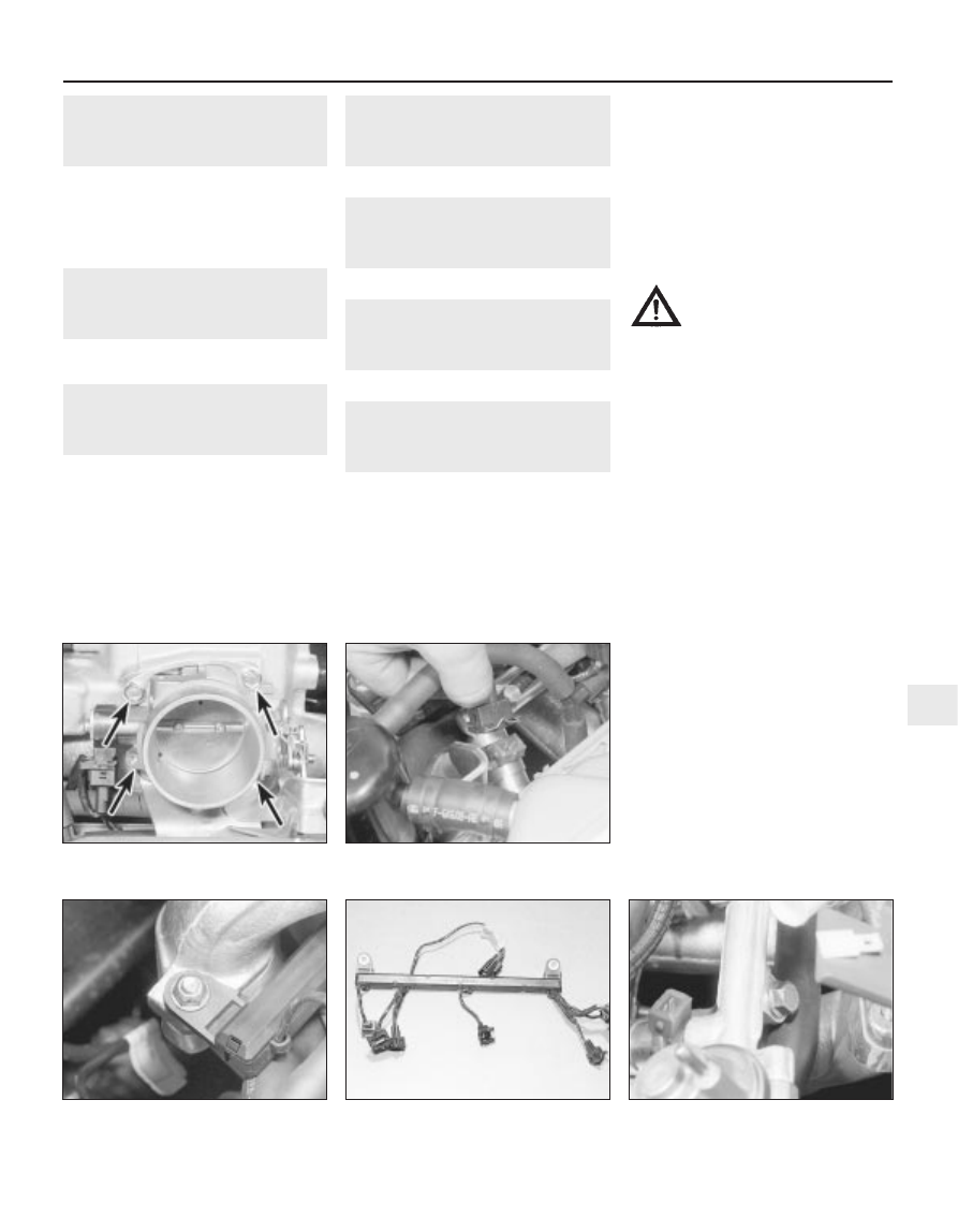
7 Unscrew the four retaining bolts, and
remove the throttle housing and its mating
face gasket (see illustration).
8 Disconnect the wiring multi-plug from the
engine coolant temperature sensor and the
inlet air temperature sensor.
9 Disconnect the wiring multi-plugs from the
fuel injectors, then undo the two retaining
bolts and detach the wiring harness from the
fuel rail (see illustrations).
10 Unscrew the fuel supply pipe at the fuel
rail. Plug the rail and pipe, to prevent further
fuel spillage and the possible ingress of dirt.
11 Disconnect the fuel return and vacuum
pipes from the pressure regulator, and catch
any fuel spillage in a clean cloth.
12 Unscrew the fuel rail securing bolts, and
carefully withdraw the rail (complete with
injectors) from the engine (see illustrations).
Fuel system - electronic fuel injection engines 4C•5
14.9b . . . unbolt the wiring harness . . .
14.9a Disconnect the wiring multi-plug
from each injector . . .
14.7 Throttle housing retaining bolt
locations (arrowed)
4C
1595Ford Fiesta Remake
14.12a Remove the fuel rail retaining
bolts . . .
14.9c . . . and remove the complete
harness