Dongfeng EQ1030T47D-820. Manual - part 13


  Index      Dongfeng     Dongfeng EQ1030T47D-820 Light Commercial Truck - service repair manual 2006 year


Search            


Content   ..  11  12  13  14   ..


Dongfeng EQ1030T47D-820. Manual - part 13


Front suspension

FA-4

Chck the upper and lower transverse arm ball head

dust proof for any damage, crack, or loose.

Warning:

If any of the above situation has happened, replace

the ball head pin in time and forbidden to drive the vehi-
cle. Otherwise, it may cause accident.

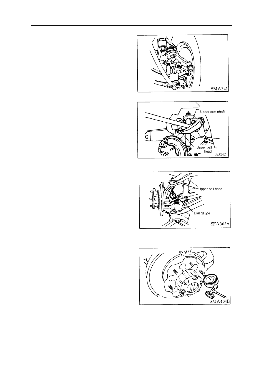
Check the vertical clearance of the ball head.

Upper ball head clearance ≤ 1.6mm

(1) Lift the front part of the vehicle and set a footstep.

(2) Fix the dial gauge to the tie rod and set the

contact of the dial gauge to the lower edge of the brake
caliper.

(3) Make sure that the front wheel is in the straight

driving line and the brake pedal has been pressed down.

(4) Insert a crowbar between the tie rod and wheel

inner felloe.

(5) At the time of pressing the crowbar, observe the

Max. read of the dial gauge.

(6) If the ball head motion clearance is beyond the

required value, disassemble the ball head and check, and
replace it if necessary.

Front wheel bearing

Check the wheel bearing for smooth operating.

Check the shaft end clearance.

It is forbidden to have clearance in the shaft end.

If the shaft end has clearance or the bearing operates unsmoothed, adjust the bearing pretightening force.

Front suspension

FA-5

As for the front wheel bearing pretightening force adjustment, please take the reference of other chapter.

Front wheel alignment

Before check the front wheel alignment, do the fol-

lowing primary inspection.

Primary inspection

1.Check the tyre for wear, and the tyre pressure.

(standard pressure: 530kPa)

2.Check the inside and outside radial runout of the

wheel assembly.

(Outside radial runout value + inside radial runout

value) × 0.5:

Radial runout limit value: 0.8mm

Lateral runout limit value: 0.8mm

3.Check the front wheel bearing for looseness.

4.Check the front suspension for looseness.

5.Check the steering pull rod for looseness.

6.Use the standard vibration to test the shock absorber

for normal work.

7.Measure the vehicle gesture (no load): =A-B mm

Reference to "Maintenance data & explanation"

(1) Shock the front part of the vehicle for 4~5 times to make the front suspension do the relative motion to

confirm the correct vehicle gesture.

(2) Measure the wheel alignment.

See "Wheel alignment" of  "Maintenance data & explanation".

(3) If the wheel alignment is not the same as the required value, adjust the vehicle gesture.

See "Wheel alignment" of "Maintenance data & explanation".

(4) Adjust the wheel alignment.

See "Wheel alignment" of "Maintenance data & explanation".

Wheel camber, caster, and king pin inclination

Before check the wheel camber, caster and king pin

inclination, set the front wheel alignment test device under
the wheel, then make the vehicle shock up and down for
several times to limit the friction force, and make sure the
vehicle gesture is correct.

Front suspension

FA-6

After the test, if it is necessary to adjust the angle, please follow the steps below:

First, check the upper and lower ball head pin for wear and looseness, the hub bearing for looseness, and the

steering kunckle for deformation.

Wheel camber (zero load)

See "maintenance data & explanation" for reference.

King pin inclination (zero load)

See "maintenance data & explanation" for reference.

Caster (zero load)

See "maintenance data & explanation" for reference.

Adjustment

The change of the wheel camber and caster is through

increase or decrease the ajusting spacer between shock
absorber and upper transverse arm shaft.

Before increase or decrease the adjusting spacer, lift

the lower transverse arm by the jack.

Front suspension

FA-7

Thickness of the adjusting spacer: 1.0mm, 1.6mm, 3.2mm

Don't use more than 3 spacers in the same place.

When assemble the spacer, insert from top to bottom.

The total thickness of the spacer should not be more than 9.6mm.

The thickness difference of the same side of the front and rear end should not be more than 4.8mm.

Follow the below steps to confirm the needed spacer thickness of adjusting wheel camber and caster:

1.Respectively increase the adjusting spacer of 1mm thickness at the same side, front and rear end, and then

the wheel camber angle of this side will reduce  0

°15´, while the caster will not change.

2.If the front end is 1mm more than the rear end adjusting spacer of the same side, the caster angle of this

side will reduce 0

°24´, while the camber angle will reduce 

0

°7´30¨.

3.If the front end is 1mm less than the rear end adjusting spacer of the same side, the caster angle of this side

will increase 0

°24´, while the camber angle will

 increase 0

°7´30¨.

4.If  the wheel alignment parameter is still incorrect after the adjustment of above, the frame has to be

adjusted.

Toe-in

1.Mark a reference line on the tyre, make the vehicle

front part on the ground, and shock it up and down for
several times to eliminate the clearance, and then set the
steering wheel to the position of front straight driving.

2.Measure the toe in

Measure A and B at the wheel midline, in the same

height.

Toe in value:

See "maintenance data & explanation" for reference.

3.Change the middle tie rod length to adjust the toe

in.

(1) Loose the lock nut.

(2) Turn the left and right joint of the same degree to

adjust the toe in.


Content   ..  11  12  13  14   ..