Dodge Sprinter. Manual - part 343


  Index      Dodge     Dodge Sprinter / Mercedes-Benz - service repair manual 2006 year


Search            


Content   ..  341  342  343  344   ..


Dodge Sprinter. Manual - part 343


(5) Remove the shift mechanism (Refer to 21 -

TRANSMISSION/TRANSAXLE/AUTOMATIC

-

NAG1/SHIFT MECHANISM - REMOVAL).

(6) Remove center floor distribution duct from the

heater housing.

INSTALLATION

(1) Install the center floor distribution duct onto

the heater housing.

(2) Install the shift mechanism (Refer to 21 -

TRANSMISSION/TRANSAXLE/AUTOMATIC

-

NAG1/SHIFT MECHANISM - INSTALLATION).

(3) Install the left and right floor distribution

ducts onto the center floor distribution duct.

(4) Install the left and right floor distribution duct

retaining screws to the instrument panel support.
Tighten the screws to 2 N·m (17 in. lbs.).

(5) Install the defroster ducts (Refer to 24 - HEAT-

ING & AIR CONDITIONING/DISTRIBUTION/DE-
FROSTER DUCTS - INSTALLATION).

(6) Install the instrument panel (Refer to 23 -

BODY/INSTRUMENT

PANEL/INSTRUMENT

PANEL ASSEMBLY - INSTALLATION).

HVAC HOUSING

REMOVAL

WARNING: To avoid personal injury or death, on
vehicles equipped with airbags, disable the supple-
mental

restraint

system

before

attempting

any

steering wheel, steering column, airbag, seat belt
tensioner, impact sensor, or instrument panel com-

ponent diagnosis or service. Disconnect and isolate
the battery negative (ground) cable, then wait two
minutes for the system capacitor to discharge
before performing further diagnosis or service. This
is the only sure way to disable the supplemental
restraint system. Failure to take the proper precau-
tions could result in accidental airbag deployment.

WARNING: Refer to the applicable warnings and
cautions for this system before performing the fol-
lowing operation (Refer to 24 - HEATING & AIR
CONDITIONING/PLUMBING - WARNINGS) and (Refer
to 24 - HEATING & AIR CONDITIONING/PLUMBING -
CAUTIONS). Failure to follow the warnings and cau-
tions could result in possible personal injury or
death.

NOTE: The HVAC housing must be removed from
the vehicle and the two halves of the housing sep-
arated for service access of the heater core, A/C
evaporator and each of the various mode doors.

(1) Recover the refrigerant from the refrigerant

system. (Refer to 24 - HEATING & AIR CONDI-
TIONING/PLUMBING - STANDARD PROCEDURE -
REFRIGERANT SYSTEM RECOVERY)

(2) Partially

drain

the

engine

cooling

system

(Refer to 7 - COOLING/ENGINE/COOLANT - STAN-
DARD PROCEDURE - DRAINING COOLING SYS-
TEM).

(3) Disconnect and isolate the negative battery

cable.

(4) Remove the air cleaner housing (Refer to 9 -

ENGINE/AIR

INTAKE

SYSTEM/AIR

CLEANER

HOUSING - REMOVAL).

(5) Remove the windshield washer reservoir (Refer

to 8 - ELECTRICAL/WIPERS/WASHERS/WASHER
RESERVOIR - REMOVAL).

(6) Remove the air filter from the ventilation hous-

ing (Refer to 24 - HEATING & AIR CONDITION-
ING/DISTRIBUTION/AIR FILTER - REMOVAL).

(7) Disconnect the wire harness and vacuum con-

nectors from the recirculation door actuator (Refer to
24 - HEATING & AIR CONDITIONING/CONTROLS/
RECIRCULATION DOOR ACTUATOR - REMOVAL).

(8) Disconnect the wire harness connector from the

blower motor resistor block (Refer to 24 - HEATING
&

AIR

CONDITIONING/CONTROLS/BLOWER

MOTOR RESISTOR BLOCK - REMOVAL).

(9) Disconnect the wire harness connector from the

blower motor (Refer to 24 - HEATING & AIR CON-
DITIONING/DISTRIBUTION/BLOWER

MOTOR

-

REMOVAL).

(10) Remove the nuts and washers that secure the

ventilation housing to the body and remove the ven-
tilation housing from the vehicle (Fig. 7).

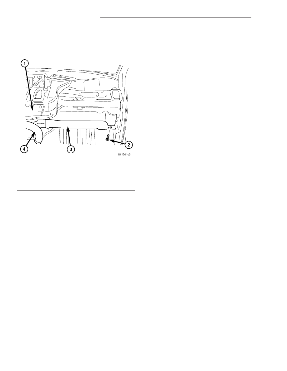
Fig. 6 Floor Distribution Duct, RH Shown, LH

Typical

1 - HEATER HOUSING
2 - SCREW (1)
3 - RH FLOOR DUCT
4 - CENTER FLOOR DUCT

24 - 48

DISTRIBUTION - FRONT

VA

(11) Disconnect the heater hoses from the heater

core.

(12) Disconnect the heater hoses from the heater

core tubes. Install plugs in, or tape over the opened
heater core tubes.

(13) Remove the two bolts securing the refrigerant

lines to the evaporator tubes and disconnect the lines
from the tubes. Install plugs in, or tape over all of
the opened refrigerant line fittings.

(14) Remove the seals from the refrigerant line fit-

tings and discard.

(15) Install plugs in, or tape over the opened

refrigerant line fittings and evaporator tubes.

(16) Remove the instrument panel from the vehicle

(Refer

to

23

-

BODY/INSTRUMENT

PANEL -

REMOVAL).

(17) Remove the defroster, floor distribution and

instrument panel ducts (Refer to 24 - HEATING &
AIR CONDITIONING/DISTRIBUTION/DEFROSTER
DUCTS - REMOVAL), (Refer to 24 - HEATING &
AIR CONDITIONING/DISTRIBUTION/FLOOR DIS-
TRIBUTION DUCTS - REMOVAL) and (Refer to 24 -
HEATING & AIR CONDITIONING/DISTRIBUTION/
INSTRUMENT PANEL DUCTS - REMOVAL).

(18) Disconnect the two bulkhead ground connec-

tions near instrument cluster area.

(19) Remove the passenger airbag bracket (Refer

to

8

-

ELECTRICAL/RESTRAINTS/PASSENGER

AIRBAG - REMOVAL).

(20) Disconnect the wire harness connector from

the evaporator temperature sensor and air outlet
temperature sensor (Fig. 8).

(21) Remove the wire harness from the bracket

located on the right side of the heater housing and
position the wire harness out of the way.

(22) Disconnect the A/C-heater control cables from

the mode door levers (Refer to 24 - HEATING & AIR
CONDITIONING/CONTROLS/MODE DOOR CABLE
- REMOVAL).

(23) Disconnect the evaporator drain tube from the

HVAC housing.

(24) Remove the five bolts securing the HVAC

housing to the body.

NOTE: Make sure that the interior is protected in
case of loss of residual fluids from the heater core
and the A/C evaporator.

(25) Remove the HVAC housing from the vehicle.

DISASSEMBLY

(1) Remove the HVAC housing from the vehicle

(Refer to 24 - HEATING & AIR CONDITIONING/
DISTRIBUTION/HVAC HOUSING - REMOVAL).

(2) Place the HVAC housing in the upright position

on a work bench, making allowance for leakage of
fluids.

Fig. 7 Ventilation Housing

1 - NUT (5)
2 - WASHER (5)
3 - VENTILATION HOUSING
4 - HOUSING COVER

Fig. 8 Heater Housing

1 - HEATER HOUSING
2 - AIR TEMP SENSOR WIRE CONNECTOR
3 - WIRE HARNESS
4 - WIRE HARNESS CONNECTOR
5 - BOLT (4)
6 - EVAP TEMP SENSOR WIRE CONNECTOR
7 - EVAPORATOR DRAIN TUBE

VA

DISTRIBUTION - FRONT

24 - 49

(3) Remove the gasket located at the A/C evapora-

tor and heater core tubes and the gasket that seals
the ventilation housing to the HVAC housing (Fig. 9).

(4) Remove the 12 screws that secure the two

housing halves together.

(5) Seperate the two housing halves.
(6) Remove the heater core from the lower hous-

ing.

(7) Remove the wire harness.
(8) Remove the three heater core tube retaining

bolts and the heater core tube assembly from the
heater core.

(9) Remove the heater core tube seals and discard.
(10) Install plug in, or tape over the opened heater

core fittings.

(11) Remove the A/C evaporator from the lower

housing.

ASSEMBLY

(1) Install the A/C evaporator into the lower hous-

ing.

(2) Remove the tape or plugs from the heater core

fittings.

(3) Lubricate two new rubber O-ring seals with

clean engine coolant and install them onto the heater
core fitting.

(4) Connect the heater core tube assembly to the

heater core and install the three retaining bolts.
Tighten the bolts to 5 N·m (45 in. lbs.).

(5) Install the wire harness.
(6) Install the heater core into the lower housing.
(7) Install the two housing halves together.
(8) Install the 12 screws that secure the two hous-

ing halves together. Tighten the screws to 2 N·m (17
in. lbs.).

(9) Install the gasket for the A/C evaporator and

heater core tube outlets and the gasket that seals the
ventilation housing to the HVAC housing.

(10) Install the HVAC housing (Refer to 24 -

HEATING & AIR CONDITIONING/DISTRIBUTION/
HVAC HOUSING - INSTALLATION).

INSTALLATION

NOTE: High pressures are produced in the refriger-
ant system when the A/C compressor is operating.
Extreme care must be exercised to make sure that
each of the refrigerant system connections is pres-
sure-tight and leak free.

(1) Position the HVAC housing to the dash panel.

Be certain that the evaporator condensate drain tube
is positioned correctly.

(2) Install the screws that secure the HVAC hous-

ing to the dash panel. Tighten the screws to 4.5 N·m
(40 in. lbs.).

(3) Connect the HVAC housing wire harness con-

nectors and install the wiring harness to the bracket.

(4) Connect the A/C-heater control cables to the

mode door levers (Refer to 24 - HEATING & AIR
CONDITIONING/CONTROLS/MODE DOOR CABLE
- INSTALLATION).

(5) Reinstall the passenger airbag bracket (Refer

to

8

-

ELECTRICAL/RESTRAINTS/PASSENGER

AIRBAG - INSTALLATION).

(6) Reconnect the two bulkhead ground connection

near the instrument cluster area.

(7) Reinstall the defroster, floor distribution and

instrument panel ducts.

(8) Reinstall the instrument panel (Refer to 23 -

BODY/INSTRUMENT

PANEL/INSTRUMENT

PANEL ASSEMBLY - INSTALLATION).

(9) Unplug or remove the tape from the opened

refrigerant line fittings.

(10) Lubricate two new rubber O-ring seals with

clean refrigerant oil and install them onto the evap-
orator core fittings.

(11) Connect the refrigerant line terminal block to

the evaporator tubes.

Fig. 9 HVAC Housing

1 - SCREW (12)
2 - UPPER HOUSING
3 - A/C EVAPORATOR
4 - EVAPORATOR O-RING SEAL (2)
5 - EVAPORATOR GASKET
6 - VENTILATION HOUSING GASKET
7 - LOWER HOUSING
8 - WIRING HARNESS
9 - BOLT (3)
10 - HEATER CORE
11 - HEATER CORE TUBE ASSEMBLY
12 - HEATER CORE TUBE GASKET
13 - HEATER CORE TUBE O-RING SEAL (2)

24 - 50

DISTRIBUTION - FRONT

VA

(12) Install the two bolts that secure the refriger-

ant line terminal block to the A/C evaporator.
Tighten the bolts to 5 N·m (45 in. lbs.).

(13) Unplug or remove the tape from the heater

core hoses and tubes.

(14) Connect the heater hoses to the heater core

tubes and install the heater hose clamps.

(15) Install the ventilation housing to the dash

panel.

(16) Install the nuts and washers that secure the

ventilation housing to the dash panel. Tighten the
nuts to 5 N·m (45 in. lbs.).

(17) Connect the wire harness connectors to the

blower motor, blower motor resistor block and the
recirculation door actuator.

(18) Connect the vacuum harness connector to the

recirculation door actuator.

(19) Install the air filter into the ventilation hous-

ing (Refer to 24 - HEATING & AIR CONDITION-
ING/DISTRIBUTION/AIR

FILTER

-

INSTALLATION).

(20) Install the windshield washer reservoir (Refer

to 8 - ELECTRICAL/WIPERS/WASHERS/WASHER
RESERVOIR - INSTALLATION).

(21) Install the air cleaner housing (Refer to 9 -

ENGINE/AIR

INTAKE

SYSTEM/AIR

CLEANER

HOUSING - INSTALLATION).

(22) Reconnect the negative battery cable.
(23) If the heater core is being replaced, flush the

cooling system (Refer to 7 - COOLING - STANDARD
PROCEDURE - COOLING SYSTEM CLEANING/
REVERSE FLUSHING).

(24) Refill the engine cooling system (Refer to 7 -

COOLING/ENGINE/COOLANT - STANDARD PRO-
CEDURE - COOLANT SYSTEM FILL).

(25) Evacuate the refrigerant system (Refer to 24 -

HEATING & AIR CONDITIONING/PLUMBING -
STANDARD PROCEDURE - REFRIGERANT SYS-
TEM EVACUATE).

(26) Charge the refrigerant system (Refer to 24 -

HEATING & AIR CONDITIONING/PLUMBING -
STANDARD PROCEDURE - REFRIGERANT SYS-
TEM CHARGE).

INSTRUMENT PANEL DUCTS

REMOVAL

(1) Remove the instrument panel (Refer to 23 -

BODY/INSTRUMENT

PANEL/INSTRUMENT

PANEL ASSEMBLY - REMOVAL).

(2) Remove the defroster ducts (Refer to 24 -

HEATING & AIR CONDITIONING/DISTRIBUTION/
DEFROSTER DUCTS - REMOVAL).

(3) Remove the floor distribution ducts (Refer to 24

- HEATING & AIR CONDITIONING/DISTRIBU-
TION/FLOOR

DISTRIBUTION

DUCTS

-

REMOVAL).

(4) If removing the right instrument panel duct,

remove the passenger air bag module and bracket
(Refer to 8 - ELECTRICAL/RESTRAINTS/PASSEN-
GER AIRBAG - REMOVAL).

(5) Remove the screws that secure the left and/or

right instrument panel duct and remove the duct(s)
as required (Fig. 10).

INSTALLATION

(1) Connect the instrument panel duct(s) to the

heater housing as required.

(2) Install the instrument panel duct retaining

screws. Tighten the screws to 2 N·m (17 in. lbs.).

(3) If servicing the right instrument panel duct,

install the passenger air bag module and bracket
(Refer to 8 - ELECTRICAL/RESTRAINTS/PASSEN-
GER AIRBAG - INSTALLATION).

(4) Install the floor distribution ducts (Refer to 24

- HEATING & AIR CONDITIONING/DISTRIBU-
TION/FLOOR DISTRIBUTION DUCTS - INSTAL-
LATION).

(5) Install the defroster ducts (Refer to 24 - HEAT-

ING & AIR CONDITIONING/DISTRIBUTION/DE-
FROSTER DUCTS - INSTALLATION).

(6) Install the instrument panel (Refer to 23 -

BODY/INSTRUMENT

PANEL/INSTRUMENT

PANEL ASSEMBLY - INSTALLATION).

Fig. 10 Instrument Panel Duct - RH Shown, LH

Typical

1 - RH DEFROSTER DUCT
2 - SCREW (2)
3 - RH INSTRUMENT PANEL DUCT
4 - RH FLOOR DISTRIBUTION DUCT
5 - CENTER FLOOR DISTRIBUTION DUCT

VA

DISTRIBUTION - FRONT

24 - 51


Content   ..  341  342  343  344   ..