Dodge Sprinter. Manual - part 338


  Index      Dodge     Dodge Sprinter / Mercedes-Benz - service repair manual 2006 year


Search            


Content   ..  336  337  338  339   ..


Dodge Sprinter. Manual - part 338


INSTALLATION

(1) Position the rear A/C condenser fan relay into

the proper receptacle of the relay block located in the
rear A/C evaporator housing.

(2) Align the A/C condenser fan relay terminals

with the terminal cavities in the relay block recepta-
cle and push down firmly on the relay until the ter-
minals are fully seated.

(3) Install the rear air filter (Refer to 24 - HEAT-

ING

&

AIR

CONDITIONING/DISTRIBUTION

-

REAR/AIR FILTER - INSTALLATION).

(4) Reconnect the negative battery cable.

A / C CONTROL MODULE

DESCRIPTION

The rear A/C control module (Fig. 5) is connected

to the rear A/C blower motor switch, rear evaporative
temperature sensor, rear A/C temperature control
and the temperature sensor.

The rear A/C control module is located in the upper

left side of the rear A/C evaporator housing.

OPERATION

The rear A/C control module is supplied fused bat-

tery power through the rear blower switch. The con-
trol module receives input signals from the rear A/C
blower motor switch, rear A/C temperature control,
rear temperature sensor and the rear evaporator
temperature sensor when the front A/C switch is
turned on. The rear A/C control module uses the

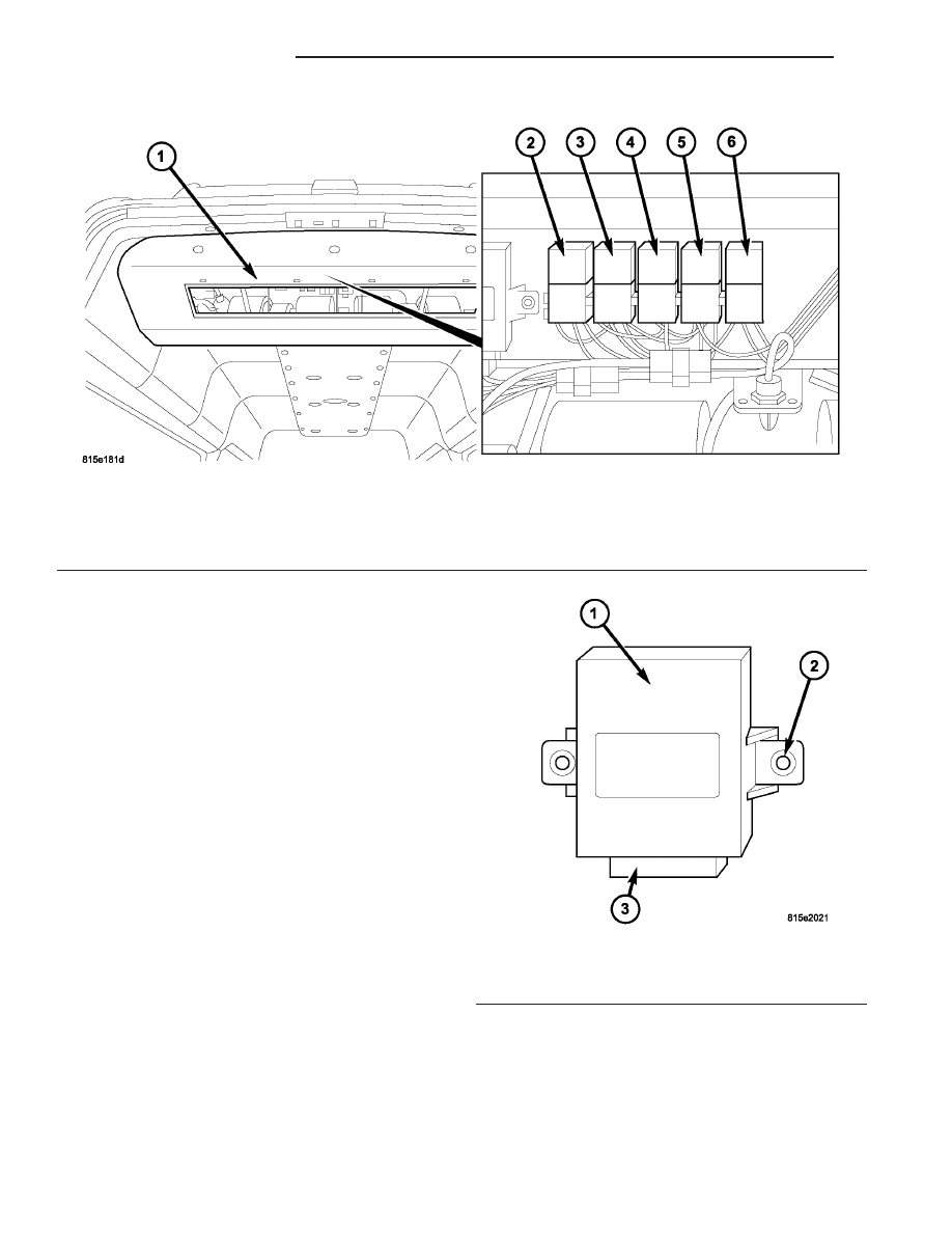
Fig. 4 Rear A/C Condenser Fan Relay

1 - REAR A/C EVAPORATOR HOUSING
2 - BLOWER MOTOR RELAY K204
3 - BLOWER MOTOR RELAY K203

4 - BLOWER MOTOR RELAY K201
5 - REAR CONDENSER FAN RELAY K205
6 - REAR COMPRESSOR RELAY K206

Fig. 5 Rear A/C Control Module

1 - REAR A/C CONTROL MODULE
2 - MOUNTING TABS
3 - WIRE HARNESS CONNECTOR

24 - 28

CONTROLS - REAR

VA

input signals to control rear blower motor speed and
output air temperature, and to prevent freezing of
the rear evaporator core.

The rear A/C control module cannot be repaired

and, if faulty or damaged, it must be replaced. Refer
to the appropriate wiring information for complete
HVAC wiring diagrams.

REMOVAL

(1) Disconnect and isolate the negative battery

cable.

(2) Remove the air filter from the rear A/C evapo-

rator housing (Refer to 24 - HEATING & AIR CON-
DITIONING/DISTRIBUTION - REAR/AIR FILTER -
REMOVAL).

(3) Reach up into the rear A/C evaporator housing

and disconnect the wire harness connector from the
rear A/C control module (Fig. 6).

(4) Remove the two screws that secure the rear

A/C control module to the rear A/C evaporator hous-
ing and remove the control module.

VA

CONTROLS - REAR

24 - 29

INSTALLATION

(1) Position the rear A/C control module to the

rear A/C evaporator housing.

(2) Install the two screws that secure the rear A/C

control module to the rear A/C evaporator housing.
Tighten the screws to 2 N·m (17 in. lbs.).

(3) Connect the wire harness connector to the rear

A/C control module.

(4) Install the rear air filter (Refer to 24 - HEAT-

ING

&

AIR

CONDITIONING/DISTRIBUTION

-

REAR/AIR FILTER - INSTALLATION).

(5) Reconnect the negative battery cable.

A / C HIGH PRESSURE
SWITCH

DESCRIPTION

The rear A/C high pressure switch provides a sig-

nal to the rear A/C control module to control rear A/C
compressor clutch engagement/disengagement and,
control rear A/C condenser cooling fan operation (Fig.
7). The rear A/C control module will disengage the
rear A/C clutch if the rear refrigerant system pres-
sure exceeds approximately 2551 kPa (370 psi).

The rear A/C high pressure switch is mounted on a

fitting located on the inlet tube of the rear A/C con-
denser.

The rear refrigerant system must be discharged

prior to removing the rear A/C high pressure
switch.

OPERATION

The contacts in the rear A/C high pressure switch

open and close causing the rear A/C control module
to turn the rear A/C clutch on and off. This prevents

Fig. 6 Rear A/C Control Module

1 - REAR A/C EVAPORATOR HOUSING
2 - REAR A/C CONTROL MODULE

3 - WIRE HARNESS CONNECTOR
4 - SCREW (2)

Fig. 7 Rear A/C High Pressure Switch

1 - REAR PRESSURE SWITCH
2 - WIRE CONNECTOR

24 - 30

CONTROLS - REAR

VA

rear A/C compressor operation when the rear dis-
charge line pressure approaches high levels, and also
reduces electrical surging from rear A/C clutch
engagement.

The rear A/C high pressure switch controls rear

A/C condenser cooling fan operation by monitoring
the rear discharge line pressure. When the rear dis-
charge pressure rises above approximately 1900 to
2200 kPa (280 to 320 psi) the rear A/C condenser
cooling fan will turn on. The rear condenser cooling
fan will turn off when the rear discharge pressure
drops to approximately 1600 kPa (235 psi).

The rear A/C high pressure switch contacts open

when the rear discharge line pressure rises above
approximately 3100 to 3375 kPa (450 to 490 psi). The
rear A/C high pressure switch contacts close when
the rear discharge line pressure drops to approxi-
mately 1860 to 2275 kPa (270 to 330 psi).

The rear A/C high pressure switch is factory-cali-

brated and cannot be adjusted or repaired and, if
faulty or damaged, it must be replaced. Refer to the
appropriate wiring information for complete HVAC
wiring diagrams.

REMOVAL

WARNING: Refer to the applicable warnings and
cautions for this system before performing the fol-
lowing operation (Refer to 24 - HEATING & AIR
CONDITIONING/PLUMBING - WARNINGS) and (Refer
to 24 - HEATING & AIR CONDITIONING/PLUMBING -
CAUTIONS). Failure to follow the warnings and cau-
tions could result in possible personal injury or
death.

(1) Disconnect and isolate the negative battery

cable.

(2) Remove the air filter from the rear A/C evapo-

rator housing (Refer to 24 - HEATING & AIR CON-
DITIONING/DISTRIBUTION - REAR/AIR FILTER -
REMOVAL).

(3) Recover the refrigerant from the rear refriger-

ant system (Refer to 24 - HEATING & AIR CONDI-
TIONING/PLUMBING - STANDARD PROCEDURE -
REFRIGERANT RECOVERY).

(4) Remove the cover from the rear A/C condenser

housing (Refer to 24 - HEATING & AIR CONDI-
TIONING/DISTRIBUTION

-

REAR/A/C

CON-

DENSER COVER - REMOVAL).

(5) Disconnect the wire harness connector from the

rear A/C high pressure switch (Fig. 8).

(6) Remove the rear A/C high pressure switch and

install a plug into, or tape over the opened rear dis-
charge line fitting.

INSTALLATION

NOTE: Replacement of the PTFE thread sealing
tape is required anytime the rear A/C high pressure
switch is removed from the rear discharge line. Fail-
ure to replace the sealing tape could result in a rear
refrigerant system leak.

(1) Remove the tape or plug from the rear dis-

charge line fitting.

(2) Install PTFE thread sealing tape onto the rear

A/C high pressure switch and install the switch onto
the rear discharge line. Tightened the A/C high pres-
sure switch to 10 N·m (88 in. lbs.).

(3) Connect the wiring harness connector to the

rear A/C high pressure switch.

(4) Reconnect the negative battery cable.
(5) Evacuate the rear refrigerant system (Refer to

24 - HEATING & AIR CONDITIONING/PLUMBING
- STANDARD PROCEDURE - REFRIGERANT SYS-
TEM EVACUATE).

(6) Charge the rear refrigerant system (Refer to 24

- HEATING & AIR CONDITIONING/PLUMBING -
STANDARD PROCEDURE - REFRIGERANT SYS-
TEM CHARGE).

(7) Install the rear air filter (Refer to 24 - HEAT-

ING

&

AIR

CONDITIONING/DISTRIBUTION

-

REAR/AIR FILTER - INSTALLATION).

(8) Install the cover onto the rear A/C condenser

housing (Refer to 24 - HEATING & AIR CONDI-
TIONING/DISTRIBUTION

-

REAR/A/C

CON-

DENSER COVER - INSTALLATION).

Fig. 8 Rear A/C High Pressure Switch

1 - REAR A/C CONDENSER
2 - WIRE HARNESS CONNECTOR
3 - REAR A/C HIGH PRESSURE SWITCH
4 - REAR DISCHARGE LINE FITTING

VA

CONTROLS - REAR

24 - 31


Content   ..  336  337  338  339   ..