Dodge Sprinter. Manual - part 287
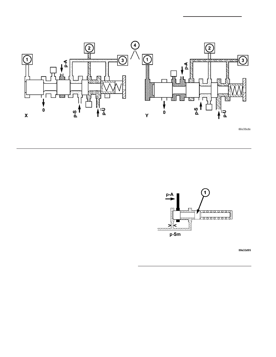
Shift Pressure Shift Valve
When the multiple-disc brake B1 (3) is activated,
the working pressure (p-A) is applied to the end face
of the 1-2 / 4-5 shift pressure shift valve (4) (Fig. 117)
via the command valve (1). Its shift state is main-
tained during the shift phase by substituting the
shift element pressure acting on its end face (and
which is variable during the shift phase) with a cor-
responding constant pressure. When the multi-plate
clutch K1 (2) is activated, the end face of the shift
valve is unpressurized during the stationary and
shift phases, so the shift state is maintained during
the shift phase in this case too.
Lubrication Pressure Regulating Valve
At the working pressure regulating valve surplus
oil is diverted to the lubrication pressure regulating
valve (1) (Fig. 118), from where the lubrication pres-
sure (p-Sm) is used in regulated amounts to supply
the transmission lubrication system including the
torque converter.
Fig. 117 Shift Pressure Shift Valve
1 - 1-2/4-5 COMMAND VALVE
2 - DRIVING CLUTCH K1
3 - HOLDING CLUTCH B1
4 - 1-2/4-5 SHIFT PRESSURE SHIFT VALVE
Fig. 118 Lubrication Pressure Regulating Valve
1 - LUBRICATION PRESSURE REGULATING VALVE
21 - 118
AUTOMATIC TRANSMISSION NAG1 - SERVICE INFORMATION
VA