Dodge Sprinter. Manual - part 227


  Index      Dodge     Dodge Sprinter / Mercedes-Benz - service repair manual 2006 year


Search            


Content   ..  225  226  227  228   ..


Dodge Sprinter. Manual - part 227


STANDARD PROCEDURE

STANDARD PROCEDURE - CHECKING AND
REPAIRING CONNECTING RODS

NOTE: Connecting rods with blue discoloration,
cross scores or notches must be replaced. Com-
pensate for different weights by milling off the bal-
ancing weight.

(1) Inspect connecting rod for discoloring, cross

scores and notches.

NOTE: Connecting rod and bearing cap are marked
in sets and attached with two sleeves.

(2) Bolt connecting rod bearing cap to connecting

rod. Tighten connecting rod bearing caps to initial

specification (Refer to 9 - ENGINE/ENGINE BLOCK/
PISTON & CONNECTING ROD - INSTALLATION).

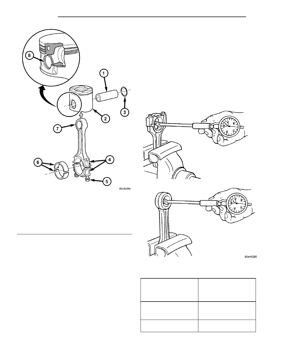
(3) Using a dial indicator, measure connecting rod

bearing basic bore, repair as necessary (Fig. 38).

NOTE: If excessive wear is present, press in new
connecting rod bushings.

(4) Measure connecting rod bushing inner diame-

ter (Fig. 38).

(5) Inspect wristpin bushing.
(6) Measure piston pin end play in connecting rod

bushing.

(7) Measure peak to valley height of connecting

rod bushing on inside.

CONNECTING ROD SPECIFICATIONS

Distance between middle
connecting rod bore to
connecting rod bushing
bore

148.970 mm to 149.030

mm

Width of connecting rod
bearing bore at connect-
ing rod bushing bore

21.940 mm to 22 mm

Connecting rod bearing
shell basic bore

51.600 mm to 51.614

mm

Fig. 37 PISTON AND CONNECTING ROD ASSEMBLY

1 - PISTON PIN
2 - PISTON
3 - SNAP RING
4 - CONNECTING ROD ALIGNMENT NUMBERS
5 - CONNECTING ROD BOLT
6 - CONNECTING ROD BEARING
7 - CONNECTING ROD
8 - SNAP RING

Fig. 38 MEASURING CONNECTING RODS

9 - 46

ENGINE

VA

Distance between middle
connecting rod bore to
connecting rod bushing
bore

148.970 mm to 149.030

mm

Allowable out-of-round-
ness and taper of basic
bore

.020 mm

Allowable twist of con-
necting rod bearing bore
to connecting rod bush-
ing bore over a length of
100 mm

.100 mm

Allowable variation of
axial parallelism of con-
necting rod bearing bore
to connecting rod bush-
ing bore over a length of
100 mm

.045 mm

Allowable difference in
weight of complete con-
necting rod of an engine

2g

Connecting rod inner
bushing

30.018 to 30.024 mm

Connecting rod outer
bushing

32.575 mm to 32.600

mm

Connecting rod basic
bore

32.500 mm to 32.525

mm

Piston pin play in con-
necting rod

.018 mm to.024 mm

Peak-to-Valley height
(Rz) of connecting rod
bushing on inside

5

Connecting rod bolt
thread

M8 x 1

STANDARD PROCEDURE - MEASURING PIS-
TON PROTRUSION

After replacing the pistons/connecting rods or

machining the engine block contact surface, it is then
necessary to measure the piston protrusion.

Measure protrusion between piston crown and cyl-

inder head contact surface without the head gasket
installed. The measurment must be carried out in
the direction of the piston pin in order to eliminate
piston rock.

(1) Measure piston protrusion at the two measur-

ing points (arrows) (Fig. 39).

Piston protrusion with new crankcase should be

0.38 - 0.62 mm.

REMOVAL

(1) Disconnect the negative battery cable.
(2) Remove the engine (Refer to 9 - ENGINE -

REMOVAL).

(3) Remove

the

cylinder

head

(Refer

to

9

-

ENGINE/CYLINDER HEAD - REMOVAL).

(4) Remove the oil pan (Refer to 9 - ENGINE/LU-

BRICATION/OIL PAN - REMOVAL).

(5) Push back on the chain tensioner and remove

the oil pump chain from the oil pump.

(6) Remove the oil pump.

NOTE: Mark the connecting rod and connecting rod
bearing cap to each other at the inlet side.

(7) Remove the connecting rod bearing cap.

NOTE: Do Not mix up the top and bottom connect-
ing rod bearing shells.

(8) Mark the connecting rod bearing shell and the

connecting rod bearing cap to each other.

Fig. 39 MEASURING PISTON PROTRUSION

1 - PISTON PROTRUSION MEASUREMENT

VA

ENGINE

9 - 47

NOTE: If the pistons are used, the direction of
travel arrows and the marking of the pistons may
no longer be visible because of carbon deposits.
The carbon deposits on the pistons must be
removed.

NOTE: If the arrows indicating the driving direction
on the piston are no longer visible, they must be
marked again.

(9) Remove the connecting rod together with the

piston through the top of the engine.

NOTE: DO NOT mix up the top and bottom connect-
ing rod bearing shells.

9 - 48

ENGINE

VA

(10) Mark the connecting rod bearing shell and

connecting rod to each other.

CAUTION: Care must be taken not to damage the
piston.

(11) Remove the piston pin circle clip. (Fig. 40).
(12) Press the piston pin out of the piston and con-

necting rod bushing. (Fig. 40).

(13) Inspect the connecting rod for wear and dam-

age.

INSTALLATION

(1) Assign piston to the cylinder bore.
(2) Using the appropriate clean engine oil, oil pis-

ton pin and connecting rod bushing.

CAUTION: Assemble the piston and connecting rod
so that the arrow is pointing in the direction of
travel (in the opposite direction of power flow). The
marking on the connecting rod is pointing toward
the inlet side.

(3) Assemble piston and connecting rod (Fig. 41).
(4) Insert piston pin by hand (Fig. 41).

CAUTION: Care must be taken not to damage the
piston.

(5) Insert circle clip of piston pin into groove on

piston (Fig. 41).

Fig. 40 PISTON AND CONNECTING ROD ASSEMBLY

1 - PISTON PIN CIRCLIP
2 - PISTON PIN
3 - PISTON ASSEMBLY
4 - CONNECTING ROD AND CAP ALIGNMENT MARKS
5 - CONNECTING ROD CAP
6 - CONNECTING ROD BOLTS
7 - ENGINE BLOCK

VA

ENGINE

9 - 49


Content   ..  225  226  227  228   ..