Dodge Sprinter. Manual - part 41


  Index      Dodge     Dodge Sprinter / Mercedes-Benz - service repair manual 2006 year


Search            


Content   ..  39  40  41  42   ..


Dodge Sprinter. Manual - part 41


BATTERY TEST RESULTS

GOOD BATTERY

Return to service

GOOD - RECHARGE

Fully charge battery and

return to service

CHARGE & RETEST

Fully charge battery and

retest battery

REPLACE BATTERY

Replace the battery and

retest complete system

BAD-CELL REPLACE

Replace the battery and

retest complete system

NOTE: The SERVICE CODE is required on every
warranty claim submitted for battery replacement.

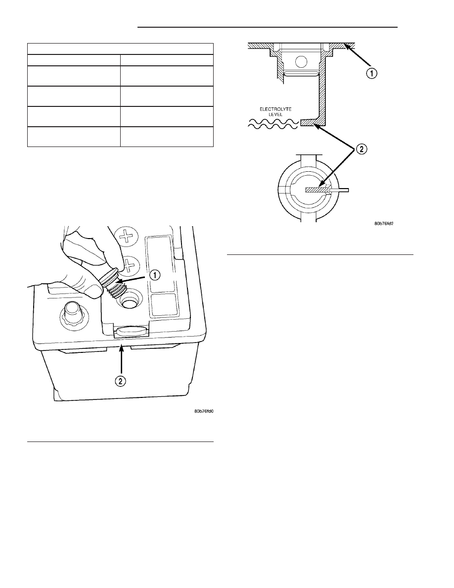
STANDARD PROCEDURE - CHECKING BATTERY
ELECTROLYTE LEVEL

(1) Remove the battery cell caps (Fig. 7).

(2) Look through the battery cap holes to deter-

mine the level of the electrolyte in the battery (Fig.
8). The electrolyte should be approximately 1 centi-
meter above the battery plates or until the hook
inside the battery cap holes is covered.

(3) Add only distilled water until the electrolyte

level is approx. one centimeter above the plates.

REMOVAL

UNDER HOOD BATTERY REMOVAL

(1) Turn the ignition switch to the Off position. Be

certain that all electrical accessories are turned off.

(2) Loosen the battery negative cable terminal

clamp pinch-bolt hex nut.

(3) Disconnect the battery negative cable terminal

clamp from the battery negative terminal post. If
necessary, use a battery terminal puller to remove
the terminal clamp from the battery post.

(4) Loosen the battery positive cable terminal

clamp pinch-bolt hex nut.

(5) Disconnect the battery positive cable terminal

clamp from the battery positive terminal post. If nec-
essary, use a battery terminal puller to remove the
terminal clamp from the battery post.

(6) Remove the battery hold downs from the bat-

tery (Refer to 8 - ELECTRICAL/BATTERY SYSTEM/
BATTERY HOLDDOWN - REMOVAL).

WARNING: WEAR A SUITABLE PAIR OF RUBBER
GLOVES (NOT THE HOUSEHOLD TYPE) WHEN
REMOVING

A

BATTERY

BY

HAND.

SAFETY

GLASSES SHOULD ALSO BE WORN. IF THE BAT-
TERY IS CRACKED OR LEAKING, THE ELECTRO-
LYTE CAN BURN THE SKIN AND EYES.

(7) Remove the battery from the battery tray.

Fig. 7 Battery Cell Caps

1 - BATTERY CELL CAP
2 - BATTERY

Fig. 8 Hook Inside Battery Cap Holes

1 - BATTERY SURFACE COVER
2 - HOOK

8F - 12

BATTERY SYSTEM

VA

AUXILIARY BATTERY REMOVAL

(1) Turn the ignition switch to the Off position. Be

certain that all electrical accessories are turned off.

(2) Remove the passenger front seat assembly.

Refer to the Body section for procedure.

(3) Remove the top cover from the seat base

assembly.

(4) Loosen the battery negative cable terminal

clamp pinch-bolt hex nut.

(5) Disconnect the battery negative cable terminal

clamp from the battery negative terminal post. If
necessary, use a battery terminal puller to remove
the terminal clamp from the battery post.

(6) Loosen the battery positive cable terminal

clamp pinch-bolt hex nut.

(7) Disconnect the battery positive cable terminal

clamp from the battery positive terminal post. If nec-
essary, use a battery terminal puller to remove the
terminal clamp from the battery post.

(8) Remove the battery hold downs from the bat-

tery (Refer to 8 - ELECTRICAL/BATTERY SYSTEM/
BATTERY HOLDDOWN - REMOVAL).

WARNING: WEAR A SUITABLE PAIR OF RUBBER
GLOVES (NOT THE HOUSEHOLD TYPE) WHEN
REMOVING

A

BATTERY

BY

HAND.

SAFETY

GLASSES SHOULD ALSO BE WORN. IF THE BAT-
TERY IS CRACKED OR LEAKING, THE ELECTRO-
LYTE CAN BURN THE SKIN AND EYES.

(9) Remove the battery from the battery tray.

INSTALLATION

UNDER HOOD BATTERY INSTALLATION

(1) Position the battery onto the battery tray.

Ensure that the battery positive and negative termi-
nal posts are correctly positioned. The battery cable
terminal clamps must reach the correct battery ter-
minal post without stretching the cables.

(2) Reinstall the battery hold downs onto the bat-

tery (Refer to 8 - ELECTRICAL/BATTERY SYSTEM/
BATTERY HOLDDOWN - INSTALLATION).

CAUTION: Be certain that the battery cable terminal
clamps are connected to the correct battery termi-
nal posts. Reverse battery polarity may damage
electrical components of the vehicle.

(3) Reconnect the battery positive cable terminal

clamp to the battery positive terminal post. Tighten
the terminal clamp pinch-bolt hex nut to 11.8 N·m
(105 in. lbs.).

(4) Reconnect the battery negative cable terminal

clamp to the battery negative terminal post. Tighten
the terminal clamp pinch-bolt hex nut to 7.9 N·m (70
in. lbs.).

(5) Apply a thin coating of petroleum jelly or chas-

sis grease to the exposed surfaces of the battery cable
terminal clamps and the battery terminal posts.

AUXILIARY BATTERY INSTALLATION

(1) Position the battery onto the battery tray.

Ensure that the battery positive and negative termi-
nal posts are correctly positioned. The battery cable
terminal clamps must reach the correct battery ter-
minal post without stretching the cables.

(2) Reinstall the battery hold downs onto the bat-

tery (Refer to 8 - ELECTRICAL/BATTERY SYSTEM/
BATTERY HOLDDOWN - INSTALLATION).

CAUTION: Be certain that the battery cable terminal
clamps are connected to the correct battery termi-
nal posts. Reverse battery polarity may damage
electrical components of the vehicle.

(3) Reconnect the battery positive cable terminal

clamp to the battery positive terminal post. Tighten
the terminal clamp pinch-bolt hex nut to 11.8 N·m
(105 in. lbs.).

(4) Reconnect the battery negative cable terminal

clamp to the battery negative terminal post. Tighten
the terminal clamp pinch-bolt hex nut to 7.9 N·m (70
in. lbs.).

(5) Apply a thin coating of petroleum jelly or chas-

sis grease to the exposed surfaces of the battery cable
terminal clamps and the battery terminal posts.

(6) Install the top cover on the seat base assembly.
(7) Install the passenger front seat assembly. Refer

to the Body section for procedure.

BATTERY HOLDDOWN

DESCRIPTION

The battery hold down hardware includes two hex

nuts with washers and two hold down brackets. The
battery hold down brackets are formed of stamped
steel. The hold down assembly is coated for corrosion
protection.

When installing a battery into the battery tray, be

certain that the hold down hardware is properly
installed and that the fasteners are tightened to the
proper specifications. Improper hold down fastener
tightness, whether too loose or too tight, can result in
damage to the battery, the vehicle or both.

REMOVAL

(1) Turn the ignition switch to the Off position. Be

certain that all electrical accessories are turned off.

(2) Remove the two nuts that secure the battery

hold down brackets to the battery tray.

(3) Remove the battery hold down brackets.

VA

BATTERY SYSTEM

8F - 13

INSTALLATION

(1) Install the battery hold down brackets.
(2) Install the two nuts that secure the battery

hold down brackets to the battery tray. Tighten to 70
in. lbs.

BATTERY CABLES

DESCRIPTION

The battery cables are large gauge, stranded cop-

per wires sheathed within a heavy plastic or syn-
thetic rubber insulating jacket. The wire used in the
battery cables combines excellent flexibility and reli-
ability with high electrical current carrying capacity.

The battery cables cannot be repaired and, if dam-

aged or faulty they must be replaced. Both the bat-
tery positive and negative cables are available for
service replacement only as a unit with the battery
positive cable wire harness or the battery negative
cable wire harness, which may include portions of
the wiring circuits for the generator and other com-
ponents on some models.

The battery cables feature a stamped brass clamp-

ing type female battery terminal crimped onto one
end of the battery cable wire and then solder-dipped.
A square headed pinch-bolt and hex nut are installed
at the open end of the female battery terminal clamp.
The battery positive cable also includes a red molded
rubber protective cover for the female battery termi-
nal clamp. Large eyelet type terminals are crimped
onto the opposite end of the battery cable wire and
then solder-dipped. The battery positive cable wires
have a red insulating jacket to provide visual identi-
fication and feature a larger female battery terminal
clamp to allow connection to the larger battery posi-
tive terminal post. The battery negative cable wires
have a black insulating jacket and a smaller female
battery terminal clamp.

OPERATION

The battery cables connect the battery terminal

posts to the vehicle electrical system. These cables
also provide a return path for electrical current gen-
erated by the charging system for restoring the volt-
age potential of the battery. The female battery
terminal clamps on the ends of the battery cable
wires provide a strong and reliable connection of the
battery cable to the battery terminal posts. The ter-
minal pinch bolts allow the female terminal clamps
to be tightened around the male terminal posts on
the top of the battery. The eyelet terminals secured
to the ends of the battery cable wires opposite the
female battery terminal clamps provide secure and
reliable connection of the battery to the vehicle elec-
trical system.

DIAGNOSIS AND TESTING - BATTERY CABLES

A voltage drop test will determine if there is exces-

sive resistance in the battery cable terminal connec-
tions or the battery cables. If excessive resistance is
found in the battery cable connections, the connec-
tion point should be disassembled, cleaned of all cor-
rosion

or

foreign

material,

then

reassembled.

Following reassembly, check the voltage drop for the
battery cable connection and the battery cable again
to confirm repair.

When performing the voltage drop test, it is impor-

tant to remember that the voltage drop is giving an
indication of the resistance between the two points at
which the voltmeter probes are attached. EXAM-
PLE: 
When testing the resistance of the battery pos-
itive cable, touch the voltmeter leads to the battery
positive cable terminal clamp and to the battery pos-
itive cable eyelet terminal at the starter solenoid
B(+) terminal stud. If you probe the battery positive
terminal post and the battery positive cable eyelet
terminal at the starter solenoid B(+) terminal stud,
you are reading the combined voltage drop in the
battery positive cable terminal clamp-to-terminal
post connection and the battery positive cable.

VOLTAGE DROP TEST

WARNING: IF THE BATTERY SHOWS SIGNS OF
FREEZING, LEAKING, LOOSE POSTS, OR LOW
ELECTROLYTE LEVEL, DO NOT TEST, ASSIST-
BOOST, OR CHARGE. THE BATTERY MAY ARC
INTERNALLY AND EXPLODE. PERSONAL INJURY
AND/OR VEHICLE DAMAGE MAY RESULT.

WARNING: EXPLOSIVE HYDROGEN GAS FORMS IN
AND AROUND THE BATTERY. DO NOT SMOKE,
USE FLAME, OR CREATE SPARKS NEAR THE BAT-
TERY. PERSONAL INJURY AND/OR VEHICLE DAM-
AGE MAY RESULT.

WARNING: THE BATTERY CONTAINS SULFURIC
ACID, WHICH IS POISONOUS AND CAUSTIC. AVOID
CONTACT WITH THE SKIN, EYES, OR CLOTHING.
IN THE EVENT OF CONTACT, FLUSH WITH WATER
AND CALL A PHYSICIAN IMMEDIATELY. KEEP OUT
OF THE REACH OF CHILDREN.

WARNING: IF THE BATTERY IS EQUIPPED WITH
REMOVABLE CELL CAPS, BE CERTAIN THAT EACH
OF THE CELL CAPS IS IN PLACE AND TIGHT
BEFORE THE BATTERY IS RETURNED TO SER-
VICE. PERSONAL INJURY AND/OR VEHICLE DAM-
AGE MAY RESULT FROM LOOSE OR MISSING
CELL CAPS.

8F - 14

BATTERY SYSTEM

VA

The following operation will require a voltmeter

accurate to 1/10 (0.10) volt. Before performing this
test, be certain that the following procedures are
accomplished:

• The battery is fully-charged and tested. (Refer to

8 - ELECTRICAL/BATTERY SYSTEM/BATTERY -
STANDARD PROCEDURE).

• Fully engage the parking brake.

• Place the automatic transmission gearshift selec-

tor lever in the Park position.

• Verify that all lamps and accessories are turned

off.

• Prevent the engine from starting.
(1) Connect the positive lead of the voltmeter to

the battery negative terminal post. Connect the neg-
ative lead of the voltmeter to the battery negative
cable terminal clamp (Fig. 9). Rotate and hold the
ignition switch in the Start position. Observe the
voltmeter. If voltage is detected, correct the poor con-
nection between the battery negative cable terminal
clamp and the battery negative terminal post.

(2) Connect the positive lead of the voltmeter to

the battery positive terminal post. Connect the nega-
tive lead of the voltmeter to the battery positive cable
terminal clamp (Fig. 10). Rotate and hold the ignition
switch in the Start position. Observe the voltmeter. If
voltage is detected, correct the poor connection
between the battery positive cable terminal clamp
and the battery positive terminal post.

(3) Connect the voltmeter to measure between the

battery positive cable terminal clamp and the starter
solenoid B(+) terminal stud (Fig. 11). Rotate and hold
the ignition switch in the Start position. Observe the
voltmeter. If the reading is above 0.2 volt, clean and
tighten the battery positive cable eyelet terminal con-
nection at the starter solenoid B(+) terminal stud.
Repeat the test. If the reading is still above 0.2 volt,
replace the faulty battery positive cable.

(4) Connect the voltmeter to measure between the

battery negative cable terminal clamp and a good
clean ground on the engine block (Fig. 12). Rotate
and hold the ignition switch in the Start position.
Observe the voltmeter. If the reading is above 0.2

Fig. 9 Test Battery Negative Connection Resistance

- Typical

1 - VOLTMETER
2 - BATTERY

Fig. 10 Test Battery Positive Connection Resistance

- Typical

1 - VOLTMETER
2 - BATTERY

Fig. 11 Test Battery Positive Cable Resistance -

Typical

1 - BATTERY
2 - VOLTMETER
3 - STARTER MOTOR

VA

BATTERY SYSTEM

8F - 15


Content   ..  39  40  41  42   ..