Dodge Sprinter. Manual - part 34


  Index      Dodge     Dodge Sprinter / Mercedes-Benz - service repair manual 2006 year


Search            


Content   ..  32  33  34  35   ..


Dodge Sprinter. Manual - part 34


(6) Press off cap at belt guide pulleys.
(7) Remove belt guide pulleys.
(8) Remove

water

pump

retaining

bolts

and

remove water pump.

INSTALLATION

NOTE: Clean all mating surfaces.

(1) Fit existing accessory drive belt pulley onto the

water pump.

(2) Properly position water pump with new gasket

to the engine and tighten bolts to 14 N·m (124 lbs.
in)., M8 (20 N·m (177 lbs. in.) (Fig. 13).

NOTE: Be sure to install the washer behind the
guide pulley to assure proper alignment.

(3) Install belt guide pulleys. Tighten bolts to 35

N·m (26 lbs. ft.) (Fig. 13).

(4) Attach the coolant hoses to the water pump

and tighten clamps (Fig. 13).

(5) Attach fuel lines to the brackets at the water

pump.

(6) Install accessory drive belt.
(7) Install viscous fan clutch.
(8) Close radiator and or engine drain plug.
(9) Refill cooling system to proper level (Refer to 7

- COOLING/ENGINE/COOLANT - STANDARD PRO-
CEDURE). Check for leaks.
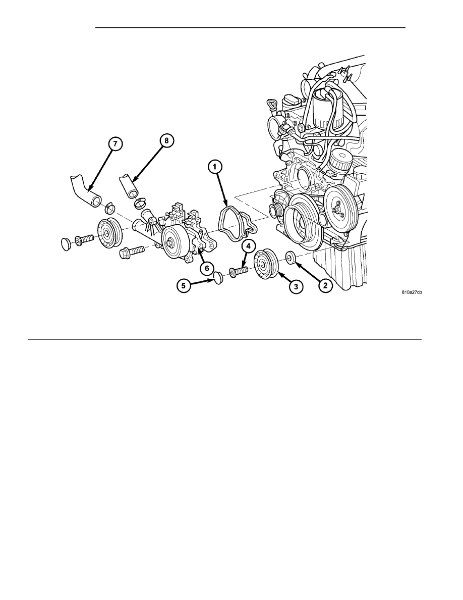
Fig. 13 WATER PUMP

1 - GASKET

5 - CAP

2 - WASHER

6 - WATER PUMP

3 - GUIDE PULLEY

7 - COOLANT HOSE

4 - BOLT

8 - COOLANT HOSE

7 - 22

ENGINE

VA

AUDIO / VIDEO

TABLE OF CONTENTS

page

page

AUDIO

SPECIAL TOOLS

AUDIO

. . . . . . . . . . . . . . . . . . . . . . . . . . . . . . . 1

ANTENNA BODY & CABLE

REMOVAL

. . . . . . . . . . . . . . . . . . . . . . . . . . . . . 1

INSTALLATION

. . . . . . . . . . . . . . . . . . . . . . . . . . 1

INSTRUMENT PANEL ANTENNA CABLE

REMOVAL

. . . . . . . . . . . . . . . . . . . . . . . . . . . . . 2

INSTALLATION

. . . . . . . . . . . . . . . . . . . . . . . . . . 2

RADIO

REMOVAL

. . . . . . . . . . . . . . . . . . . . . . . . . . . . . 2

INSTALLATION

. . . . . . . . . . . . . . . . . . . . . . . . . . 2

SPEAKER

REMOVAL

. . . . . . . . . . . . . . . . . . . . . . . . . . . . . 2

INSTALLATION

. . . . . . . . . . . . . . . . . . . . . . . . . . 3

AUDIO

SPECIAL TOOLS

AUDIO

SPECIAL TOOL CROSS REFERENCE CHART

MB

TOOL #

MILLER
TOOL #

DESCRIPTION

000 589

88 63 00

9241

RADIO EXTRACTION
TOOL

ANTENNA BODY & CABLE

REMOVAL

(1) Disconnect and isolate the battery negative

cable.

(2) Remove the portion of the headliner over the

front seat passengers (Refer to 23 - BODY/INTERI-
OR/HEADLINER - REMOVAL).

(3) Disconnect the antenna and electrical connec-

tions near the windshield (Fig. 1).

(4) Remove the mounting nut.
(5) Remove the antenna assembly from the roof

and pull wire harness and cable through roof open-
ing.

INSTALLATION

(1) Feed wire harness and cable through roof open-

ing and position antenna to roof panel.

(2) Install and tighten antenna mounting nut.
(3) Connect the antenna and electrical connections

near the windshield.

(4) Install the headliner (Refer to 23 - BODY/IN-

TERIOR/HEADLINER - INSTALLATION).

(5) Connect the battery negative cable.

Fig. 1 ANTENNA CABLE

1 - ROOF PANEL
2 - MOUNTING NUT
3 - ANTENNA CABLE
4 - ELECTRICAL CONNECTOR
5 - INSTRUMENT PANEL ANTENNA CABLE

VA

AUDIO/VIDEO

8A - 1

INSTRUMENT PANEL
ANTENNA CABLE

REMOVAL

(1) Disconnect and isolate the battery negative

cable.

(2) Remove the A-pillar trim (Refer to 23 - BODY/

INTERIOR/A-PILLAR TRIM - REMOVAL).

(3) Remove the portion of the headliner over the

front seat passengers (Refer to 23 - BODY/INTERI-
OR/HEADLINER - REMOVAL).

(4) Disconnect the antenna and electrical connec-

tions near the windshield.

(5) Remove the glove box (Refer to 23 - BODY/IN-

STRUMENT PANEL/GLOVE BOX - REMOVAL).

(6) Remove the radio (Refer to 8 - ELECTRICAL/

AUDIO/RADIO - REMOVAL).

(7) Cut both ends of existing cable close to the

instrument panel (Fig. 2).

INSTALLATION

(1) Insert new cable through glove box opening to

the radio opening in the instrument panel.

(2) Route cable up the A-pillar and connect to the

antenna body and cable.

(3) Connect the antenna and electrical connections

near the windshield.

(4) Attach antenna cable to instrument panel wire

harness.

(5) Install glove box (Refer to 23 - BODY/INSTRU-

MENT PANEL/GLOVE BOX - INSTALLATION).

(6) Install the headliner (Refer to 23 - BODY/IN-

TERIOR/HEADLINER - INSTALLATION).

(7) Install the A-pillar trim (Refer to 23 - BODY/

INTERIOR/A-PILLAR TRIM - INSTALLATION).

(8) Install the radio (Refer to 8 - ELECTRICAL/

AUDIO/RADIO - INSTALLATION).

(9) Connect the battery negative cable.

RADIO

REMOVAL

(1) Disconnect and isolate the battery negative

cable.

(2) Using special tool 9241 or equivalent, insert

one into each slot on the face of the radio (Fig. 3).

(3) Disconnect wire harness connector and antenna

from radio.

INSTALLATION

(1) Connect wire harness connector and antenna to

radio.

(2) Position radio to instrument panel and push

into place.

(3) Connect battery negative cable.

SPEAKER

REMOVAL

(1) Disconnect and isolate the battery cable.
(2) Remove the A-pillar trim (Refer to 23 - BODY/

INTERIOR/A-PILLAR TRIM - REMOVAL).

(3) Remove speaker grill (Fig. 4).

Fig. 2 INSTRUMENT PANEL ANTENNA CABLE

Fig. 3 RADIO

1 - SPECIAL TOOL 9241
2 - RADIO
3 - RETAINING TAB

8A - 2

AUDIO/VIDEO

VA

(4) Using a trim stick (C-4755 or equivalent), pry

up on the speaker.

(5) Disconnect electrical harness connector and

remove speaker.

INSTALLATION

(1) Install wire harness connector.
(2) Place speaker into instrument panel.
(3) Install speaker grille.
(4) Install the A-pillar trim (Refer to 23 - BODY/

INTERIOR/A-PILLAR TRIM - INSTALLATION).

(5) Connect the battery negative cable.

Fig. 4 INSTRUMENT PANEL SPEAKER

VA

AUDIO/VIDEO

8A - 3


Content   ..  32  33  34  35   ..