Dodge Caliber. Manual - part 95


  Index      Dodge     Dodge Caliber - service repair manual 2007 year


Search            


Content   ..  93  94  95  96   ..


Dodge Caliber. Manual - part 95


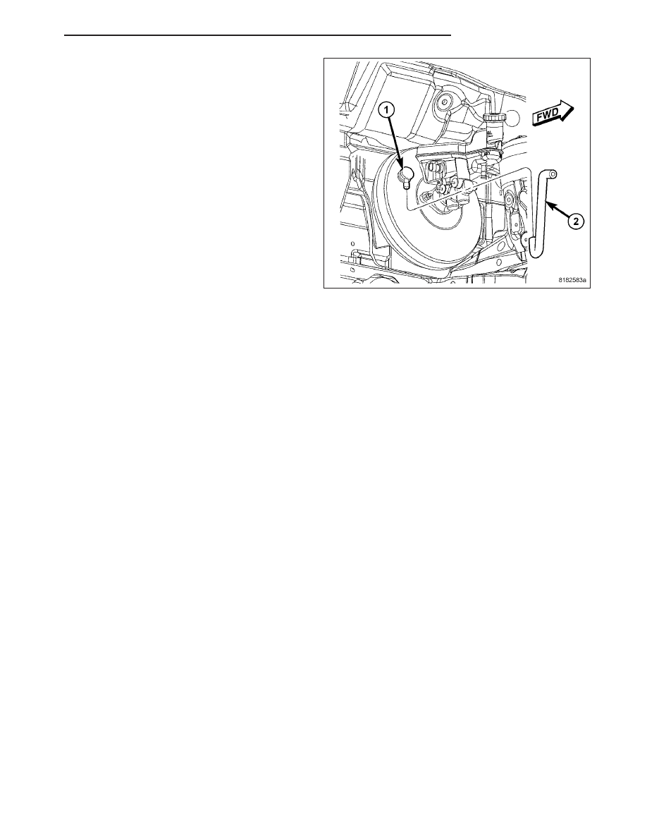
CAUTION: When installing the vacuum hose on
the check valve (1), make sure the hose is routed
properly to avoid possible contact with unfriendly
surfaces.

10. Connect the vacuum hose (2) to the vacuum

check valve (1).

11. Install the master cylinder. (Refer to 5 - BRAKES/

HYDRAULIC/MECHANICAL/MASTER CYLINDER
- INSTALLATION)

12. Connect the battery negative cable to its post on

the battery.

13. Bleed the base brake system if necessary. (Refer

to 5 - BRAKES - STANDARD PROCEDURE)

14. Road test the vehicle to ensure proper operation

of the brakes.

PM

BRAKES - BASE

5 - 81

VALVE-PROPORTIONING

DESCRIPTION

NOTE: Only vehicles without antilock brakes have proportioning valves. Vehicles with antilock brakes have
Electronic Variable Brake Proportioning (EVBP) that is built into the Integrated Control Unit (ICU).

On the non-antilock master cylinder (1), two screw-in
proportioning valves (2, 3) are screwed directly into
the rear brake outlet ports. The chassis brake tubes
leading to the rear brakes attach to the outlets of the
proportioning valves. One proportioning valve controls
each rear brake.

The proportioning valves are not identical and cannot
be interchanged. The proportioning valve that threads
into the primary port (3) has M10 x 1 threads going
into the master cylinder (1). The proportioning valve
that threads into the secondary port (2) has M12 x 1
threads going into the master cylinder (1).

OPERATION

Proportioning valves balance front to rear braking by controlling the brake fluid hydraulic pressure to the rear brakes
above a preset level (split point). Under light pedal application, the proportioning valve allows normal fluid flow to the
rear brakes. Under higher pedal effort, the valve reduces fluid pressure to the rear brakes. This helps prevent rear
wheel skid tendencies.

REMOVAL

NOTE: Before proceeding, (Refer to 5 - BRAKES - WARNING) (Refer to 5 - BRAKES - CAUTION).

1. Using a brake pedal holder, depress the brake

pedal past its first one inch (25 mm) of travel and
hold it in this position. This will isolate the master
cylinder from the brake hydraulic system and will
not allow the brake fluid to drain out of the master
cylinder reservoir.

5 - 82

BRAKES - BASE

PM

NOTE: To access the lower (left rear) proportion-
ing valve, it may help to remove the air cleaner
cover and hose to the throttle body.

2. Disconnect the brake tube (1 or 2) from the propor-

tioning valve requiring removal.

3. Unscrew the proportioning valve (2 or 3) from the

master cylinder (1).

PM

BRAKES - BASE

5 - 83

INSTALLATION

1. Install the proportioning valve (2 or 3) in its master

cylinder (1) port. Tighten the proportioning valve to
17 N·m (150 in. lbs.).

2. Install the correct brake tube (1 or 2) to the propor-

tioning valve. Tighten the tube nut to 30 N·m (22 ft.
lbs.).

5 - 84

BRAKES - BASE

PM


Content   ..  93  94  95  96   ..