Dodge Durango (HB). Manual - part 983
P2173-HIGH AIRFLOW/VACUUM LEAK DETECTED (SLOW ACCUMULATION) (CONTINUED)
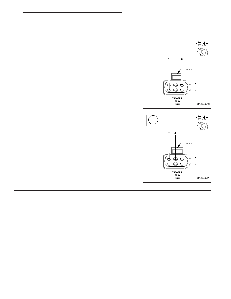
7.
TP SENSOR
Connect the C2 PCM harness connector.
Ignition on, engine not running.
With a scan tool, monitor the TP Sensor voltage.
Connect a jumper wire between the (K22) TP Sensor No.1 Signal cir-
cuit and the (K922) Sensor Return circuit in the Throttle Body harness
connector.
TP Sensor No.1 voltage should start at approximately 4.8 volts and
decrease to 0.2 of a volt.
Connect a jumper wire between the (K122) TP Sensor No.2 Signal cir-
cuit and the (F855) 5-volt Supply circuit in the Throttle Body harness
connector.
TP Sensor No.2 voltage should start at approximately 0 volts and
increase to 4.8 to 5.2 volts.
Does the TP Sensor voltage change to the appropriate voltage
with the jumper wire installed?
Yes
>> Disconnect the Battery before replacing the Throttle Body
Assembly. Replace the Throttle Body Assembly. After
installation is complete, use a scan tool and select the
ETC RELEARN function
Perform the POWERTRAIN VERIFICATION TEST. (Refer
to 9 - ENGINE - STANDARD PROCEDURE)
No
>> Go To 8
HB
ENGINE ELECTRICAL DIAGNOSTICS
9 - 931