Dodge Durango (HB). Manual - part 982
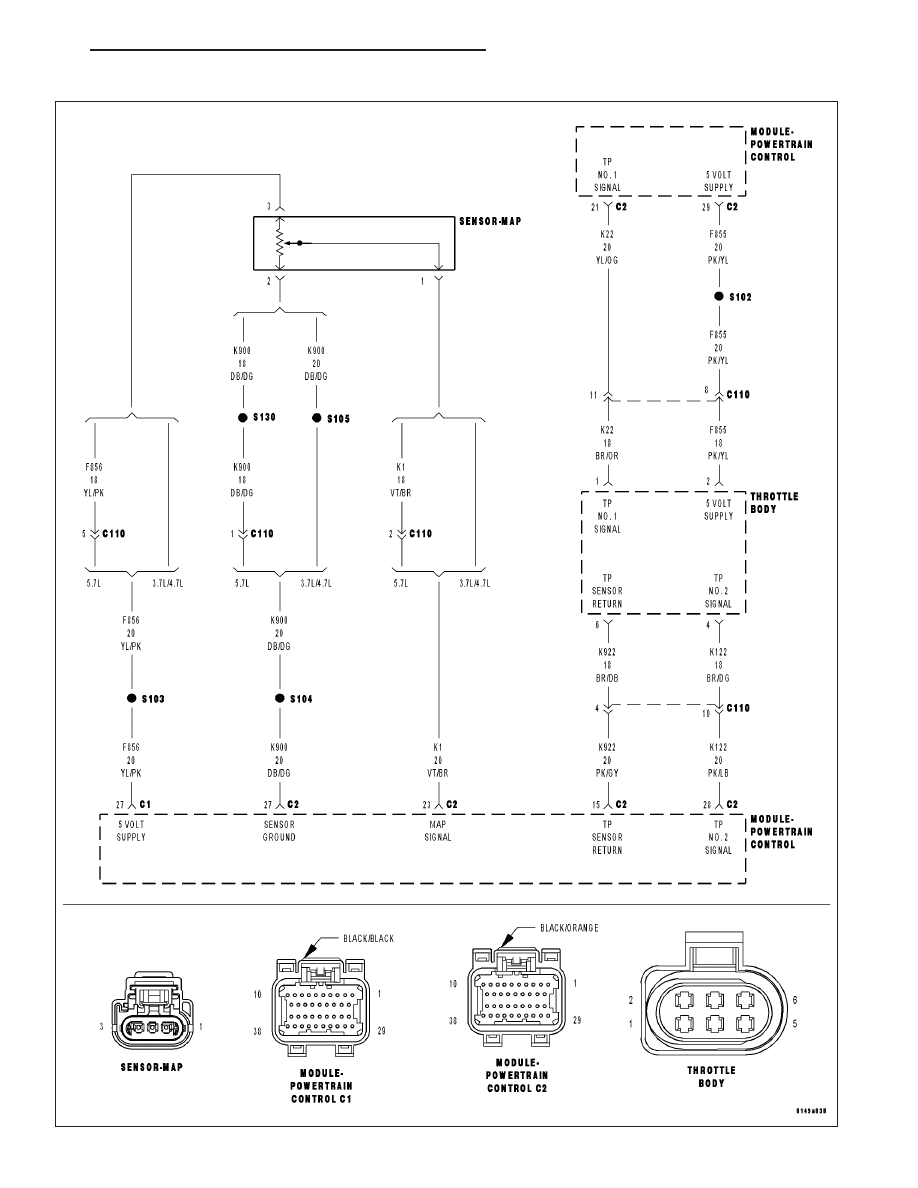
P2173-HIGH AIRFLOW/VACUUM LEAK DETECTED (SLOW ACCUMULATION)
HB
ENGINE ELECTRICAL DIAGNOSTICS
9 - 927
|
|
|
P2173-HIGH AIRFLOW/VACUUM LEAK DETECTED (SLOW ACCUMULATION) HB ENGINE ELECTRICAL DIAGNOSTICS 9 - 927 |