Index Dodge Dodge Durango (HB) - service repair manual 2005 year
Search
Content .. 945 946 947 948 ..
Dodge Durango (HB). Manual - part 947
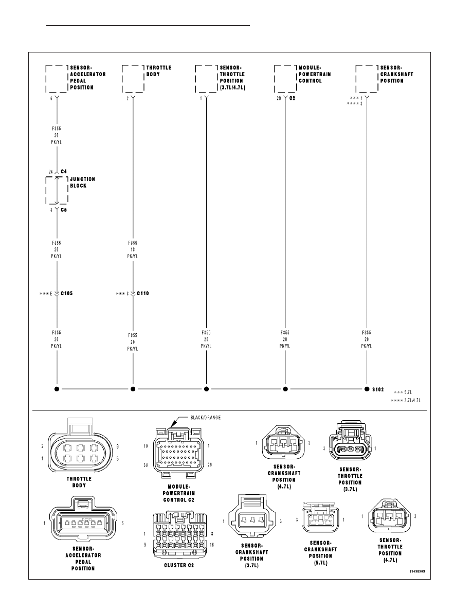
P1618-SENSOR REFERENCE VOLTAGE 1 CIRCUIT ERRATIC
HB
ENGINE ELECTRICAL DIAGNOSTICS
9 - 787