Dodge Durango (HB). Manual - part 945


  Index      Dodge     Dodge Durango (HB) - service repair manual 2005 year


Search            


Content   ..  943  944  945  946   ..


Dodge Durango (HB). Manual - part 945


P1593-SPEED CONTROL SWITCH 1 STUCK (3.7L, 4.7L) (CONTINUED)

4.

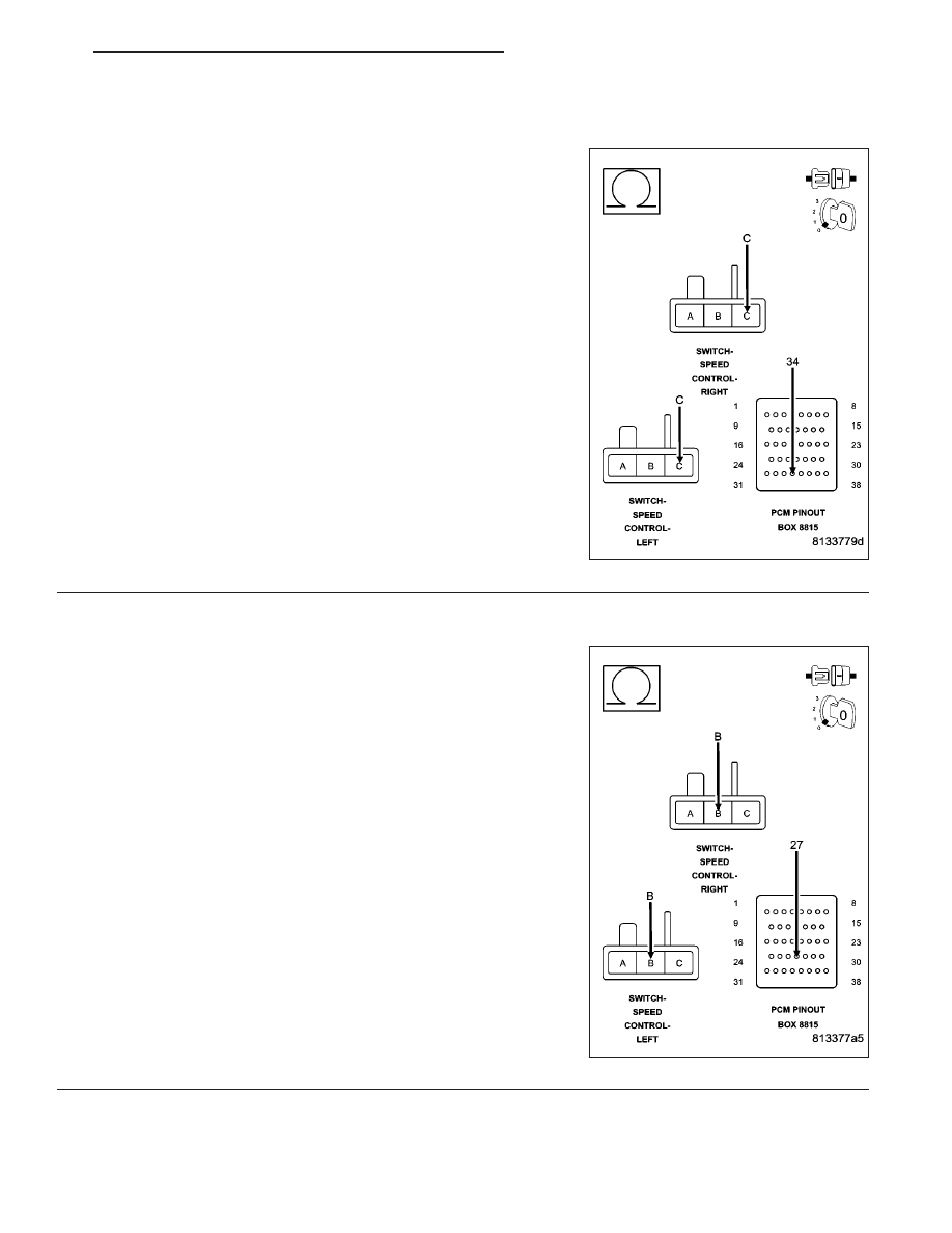
(V37) S/C SWITCH NO.1 SIGNAL CIRCUIT OPEN

NOTE: The measurement must be taken from both Speed Control
Switch harness connectors.
Turn the ignition off.

CAUTION: Do not probe the PCM harness connectors. Probing
the PCM harness connectors will damage the PCM terminals
resulting in poor terminal to pin connection. Install Miller Special
Tool #8815 to perform diagnosis.
Measure the resistance of the (V37) S/C Switch No.1 Signal circuit
from the Speed Control harness connector to the appropriate terminal
of special tool #8815.

Is the resistance below 5.0 ohms for both measurements?

Yes

>> Go To 5

No

>> Repair the open in the (V37) S/C Switch No.1 Signal cir-

cuit.

Perform the POWERTRAIN VERIFICATION TEST. (Refer
to 9 - ENGINE - STANDARD PROCEDURE)

5.

(K900) SENSOR GROUND CIRCUIT OPEN

NOTE: The measurement must be taken from both Speed Control
Switch harness connectors.
Measure the resistance of the (K900) Sensor ground circuit from the
Speed Control harness connector to the appropriate terminal of special
tool #8815.

Is the resistance below 5.0 ohms for both measurements?

Yes

>> Go To 6

No

>> Repair the open in the (K900) Sensor ground circuit.

Perform the POWERTRAIN VERIFICATION TEST. (Refer
to 9 - ENGINE - STANDARD PROCEDURE)

HB

ENGINE ELECTRICAL DIAGNOSTICS

9 - 779

P1593-SPEED CONTROL SWITCH 1 STUCK (3.7L, 4.7L) (CONTINUED)

6.

(V37) S/C SWITCH NO.1 SIGNAL CIRCUIT SHORTED TO GROUND

Measure the resistance between ground and the (V37) S/C Switch
No.1 Signal circuit in the Speed Control harness connector.

Is the resistance below 100 ohms?

Yes

>> Repair the short to ground in the (V37) S/C Switch No.1

Signal circuit.

Perform the POWERTRAIN VERIFICATION TEST. (Refer
to 9 - ENGINE - STANDARD PROCEDURE)

No

>> Go To 7

7.

(V37) S/C SWITCH NO.1 SIGNAL CIRCUIT SHORTED TO THE (K900) SENSOR GROUND CIRCUIT

Measure the resistance between the (V37) S/C Switch No.1 Signal cir-
cuit and the (K900) Sensor ground circuit in the Speed Control har-
ness connector.

Is the resistance below 5.0 ohms?

Yes

>> Repair the short between the (V37) S/C Switch No.1 Sig-

nal circuit and the (K900) Sensor ground circuit.

Perform the POWERTRAIN VERIFICATION TEST. (Refer
to 9 - ENGINE - STANDARD PROCEDURE)

No

>> Go To 8

8.

PCM

NOTE: Before continuing, check the PCM harness connector terminals for corrosion, damage, or terminal
push out. Repair as necessary.
Using the schematics as a guide, inspect the wire harness and connectors. Pay particular attention to all Power and
Ground circuits.

Were there any problems found?

Yes

>> Repair as necessary.

Perform the POWERTRAIN VERIFICATION TEST. (Refer to 9 - ENGINE - STANDARD PROCEDURE)

No

>> Replace and program the Powertrain Control Module per Service Information.

Perform the POWERTRAIN VERIFICATION TEST. (Refer to 9 - ENGINE - STANDARD PROCEDURE)

9 - 780

ENGINE ELECTRICAL DIAGNOSTICS

HB

P1602–PCM NOT PROGRAMMED

For the Engine circuit diagram (Refer to 9 - ENGINE - SCHEMATICS AND DIAGRAMS).

For a complete wiring diagram Refer to Section 8W.

When Monitored:
Ignition on and battery voltage greater than 10 volts.

Set Condition:
The PCM has not been programmed.

Possible Causes

PCM

Always perform the Pre-Diagnostic Troubleshooting procedure before proceeding. (Refer to 9 - ENGINE -
DIAGNOSIS AND TESTING).

Diagnostic Test

1.

PCM PROGRAMMED

Ignition on, engine not running.

With a scan tool, erase DTCs.

With a scan tool program the PCM.

Start the engine.

Allow the engine to reach normal operating temperature.

With a scan tool, read DTCs.

Does the DTC reset?

Yes

>> Replace and program the Powertrain Control Module per Service Information.

Perform the POWERTRAIN VERIFICATION TEST. (Refer to 9 - ENGINE - STANDARD PROCEDURE)

No

>> The PCM has been successfully programmed. Test is complete.

Perform the POWERTRAIN VERIFICATION TEST. (Refer to 9 - ENGINE - STANDARD PROCEDURE)

HB

ENGINE ELECTRICAL DIAGNOSTICS

9 - 781

P1603-PCM INTERNAL DUAL-PORT RAM COMMUNICATION FAILURE

For the Engine circuit diagram (Refer to 9 - ENGINE - SCHEMATICS AND DIAGRAMS).

For a complete wiring diagram Refer to Section 8W.

When Monitored:
Ignition on and battery voltage greater than 10 volts.

Set Condition:
Internal PCM failure detected. One Trip Fault. Three good trips to turn off the MIL.

Possible Causes

PCM FUSED IGNITION SWITCH CIRCUITS

PCM INTERNAL

Always perform the Pre-Diagnostic Troubleshooting procedure before proceeding. (Refer to 9 - ENGINE -
DIAGNOSIS AND TESTING).

Diagnostic Test

1.

PCM IGNITION CIRCUITS

Turn the ignition off.

Disconnect the C1 PCM harness connector.

Ignition on, engine not running.

CAUTION: Do not probe the PCM harness connectors. Probing
the PCM harness connectors will damage the PCM terminals
resulting in poor terminal to pin connection. Install Miller Special
Tool #8815 to perform diagnosis.
With a 12-volt test light connected to ground and with special tool
#8815 installed, probe the (F1), (F202), and (F924) Fused Ignition
Switch circuits.

Perform the above check with the Ignition key in the off lock position,
Ignition on, engine not running position, and during cranking.

Wiggle the related wire harness while probing the special tool with the
test light to try to interrupt the circuit.

Does the test light illuminate brightly?

Yes

>> Go To 2

No

>> Repair the open or excessive resistance in the (F1), (F202), and (F924) Fused Ignition Switch (Offf,

Run, Start) circuits. Inspect the related fuse, if the fuse is open check the circuits for a short to ground.

Perform the POWERTRAIN VERIFICATION TEST. (Refer to 9 - ENGINE - STANDARD PROCEDURE)

9 - 782

ENGINE ELECTRICAL DIAGNOSTICS

HB


Content   ..  943  944  945  946   ..