Index Dodge Dodge Durango (HB) - service repair manual 2005 year
Search
Content .. 926 927 928 929 ..
Dodge Durango (HB). Manual - part 928
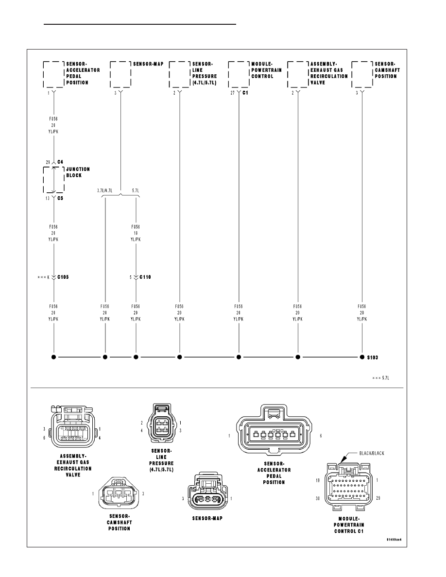
P0653-SENSOR REFERENCE VOLTAGE 2 CIRCUIT HIGH
HB
ENGINE ELECTRICAL DIAGNOSTICS
9 - 711