Dodge Durango (HB). Manual - part 882
P0481-COOLING FAN 2 CONTROL CIRCUIT (CONTINUED)
3.
HIGH SPEED RADIATOR FAN RELAY RESISTANCE
Measure the resistance of the High Speed Radiator Fan Relay Coil.
Is the resistance between 60 to 80 ohms?
Yes
>> Go To 4
No
>> Replace the Relay.
Perform BODY VERIFICATION TEST-VER 1. (Refer to 8 - ELECTRICAL/ELECTRONIC CONTROL
MODULES/FRONT CONTROL MODULE - DIAGNOSIS AND TESTING)
4.
(N112) COOLING FAN NO.2 CONTROL CIRCUIT OPEN
Disconnect the IPM FCM 49 way harness connector.
Measure the resistance of the (N112) Cooling Fan No.2 Relay Control circuit from the Relay connection to the IPM
FCM 49 way harness connector.
Is the resistance below 5.0 ohms?
Yes
>> Go To 5
No
>> Repair the open in the (N112) Cooling Fan No.2 Relay Control circuit.
Perform BODY VERIFICATION TEST-VER 1. (Refer to 8 - ELECTRICAL/ELECTRONIC CONTROL
MODULES/FRONT CONTROL MODULE - DIAGNOSIS AND TESTING)
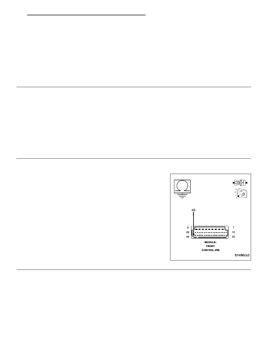
5.
(N112) COOLING FAN NO.2 CONTROL CIRCUIT SHORTED TO GROUND
Measure the resistance between ground and the (N112) Cooling Fan
No.2 Relay Control circuit at the IPM FCM 49 way harness connector.
Is the resistance below 100 ohms?
Yes
>> Repair the short to ground in the (N112) Cooling Fan No.2
Relay Control circuit.
Perform BODY VERIFICATION TEST-VER 1. (Refer to 8 -
ELECTRICAL/ELECTRONIC
CONTROL
MODULES/
FRONT CONTROL MODULE - DIAGNOSIS AND TEST-
ING)
No
>> Go To 6
HB
ENGINE ELECTRICAL DIAGNOSTICS
9 - 527