Dodge Durango (HB). Manual - part 796
P0138-O2 SENSOR 1/2 CIRCUIT HIGH (CONTINUED)
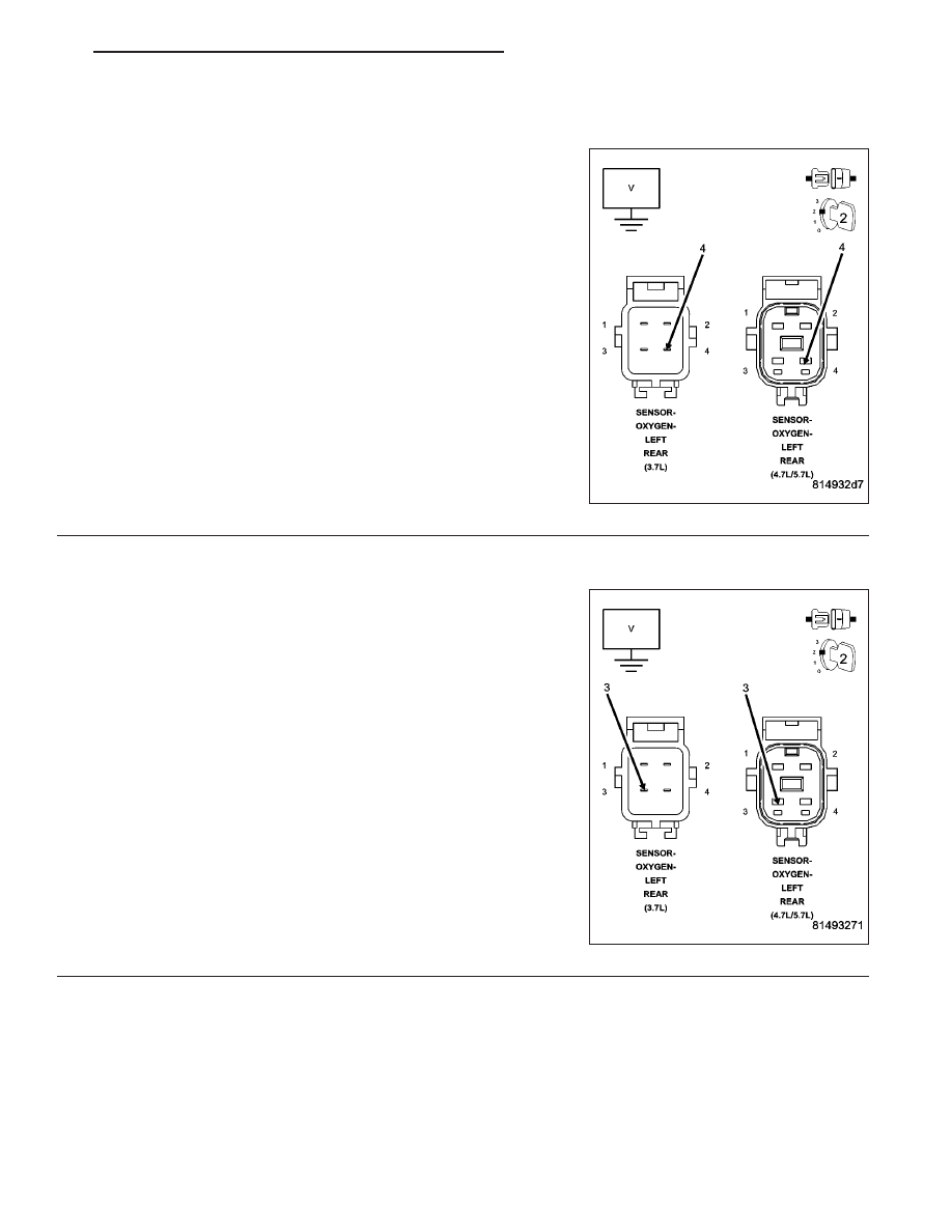
2.
(K141) O2 1/2 SIGNAL CIRCUIT SHORTED TO BATTERY VOLTAGE
Start the engine and allow the engine to idle.
Disconnect the 1/2 O2 Sensor harness connector.
Measure the voltage on the (K141) O2 Sensor 1/2 Signal circuit in the
O2 Sensor harness connector.
NOTE: Measure the voltage in reference to ground, not the (K904)
O2 Return Downstream circuit.
Is the voltage above 0 volts?
Yes
>> Repair the short to battery voltage in the (K141) O2 Sen-
sor 1/2 Signal circuit.
Perform the POWERTRAIN VERIFICATION TEST. (Refer
to 9 - ENGINE - STANDARD PROCEDURE)
No
>> Go To 3
3.
(K904) O2 RETURN DOWNSTREAM CIRCUIT SHORTED TO BATTERY VOLTAGE
Turn the ignition off.
Disconnect the C2 PCM harness connector.
Ignition on, engine not running.
Measure the voltage on the (K904) O2 Return Downstream circuit in
the O2 Sensor harness connector.
Is there any voltage present?
Yes
>> Repair the short to battery voltage in the (K904) O2
Return Downstream circuit.
Perform the POWERTRAIN VERIFICATION TEST. (Refer
to 9 - ENGINE - STANDARD PROCEDURE)
No
>> Go To 4
HB
ENGINE ELECTRICAL DIAGNOSTICS
9 - 183