Dodge Durango (HB). Manual - part 795
P0137-O2 SENSOR 1/2 CIRCUIT LOW (CONTINUED)
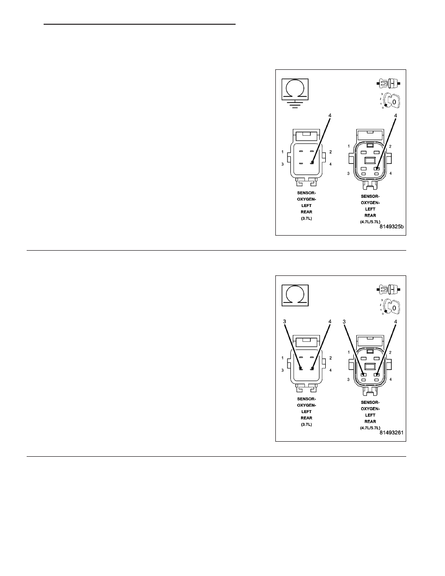
5.
(K141) O2 1/2 SIGNAL CIRCUIT SHORTED TO GROUND
Turn the ignition off.
Disconnect the C1 and C2 PCM harness connectors.
Measure the resistance between ground and the (K141) O2 1/2 Signal
circuit in the O2 Sensor harness connector.
Is the resistance below 100 ohms?
Yes
>> Repair the short to ground in the (K141) O2 1/2 Signal cir-
cuit.
Perform the POWERTRAIN VERIFICATION TEST. (Refer
to 9 - ENGINE - STANDARD PROCEDURE)
No
>> Go To 6
6.
(K141) O2 1/2 SIGNAL CIRCUIT SHORTED TO THE (K904) O2 RETURN DOWNSTREAM CIRCUIT
Measure the resistance between the (K141) O2 1/2 Signal circuit and
the (K904) O2 Return Downstream circuit in the O2 Sensor harness
connector.
Is the resistance below 100 ohms?
Yes
>> Repair the short between the (K904) O2 Return Down-
stream circuit and the (K141) O2 1/2 Signal circuit.
Perform the POWERTRAIN VERIFICATION TEST. (Refer
to 9 - ENGINE - STANDARD PROCEDURE)
No
>> Go To 7
HB
ENGINE ELECTRICAL DIAGNOSTICS
9 - 179